Showing posts with label radio. Show all posts

Thursday, October 17, 2013

VHF upgrade project

Please welcome new contributors Rick & Dar aboard m/v September Dream!  I think you will enjoy following along with them as they cruise their Mainship 34 from Kemptville, Ontario to their intended destination of the Bahamas.

But for today, their first contribution to this site is the installation of a new VHF, complete with a remote speaker/mic/control:
The downtime from travelling while visiting Dar's sister has given me some time to get some work done on a couple projects.

The first project that I worked on was the completion of my VHF radio upgrade.

When we bought the boat it came with two VHF radios that were both more than a decade old.  Besides not having DSC (Digital Selective Calling) capabilities, the radio on the flybridge was starting to die.

I decided to replace both with a Standard Horizon GX-2150+, which not only is a modern DSC capable radio, but also has AIS (Automatic Identification System) receive capabilities.

Rather than go with two VHF radios again, I decided to go with a single radio, located at the lower helm, and use a RAM3 CMP-30 remote mic for the flybridge.  We still had an old VHF handheld for a backup, but I picked up a new Standard Horizon HX-290 as a primary backup, as well as a radio to use on the flybridge until I finished the RAM3 installation.

Another side benefit of going with the single radio is that it freed up one of the antenna mounts that can now be re-purposed, and will eventually be used as a mount point for an Amateur Radio HF antenna.

Installing the GX-2150+ at the lower helm was relatively easy.  It was pretty much a straight swap out for the radio that was at the lower helm, and I completed that the week before Canada Day.

To finish the project though meant that I had some cable runs to do between the flybridge and the lower helm.  First I had to run the interface cable between the radio and the remote mic.  Second I had to run an NMEA cable to interface between the chartplotter and the radio.  In order to do the AIS receive function, the radio needs to have GPS data.  As well, it also sends the AIS target information back to the chart plotter to be displayed as a data layer overlay.

Finally, I had to run a cable to connect the PA/Fog-horn, which was previously connected to the flybridge radio, to connect it to the new radio at the lower helm.

The first step was gaining access to the cabling space under the flybridge dash.  Imagine my surprise when I cracked the panel and found this;

Flybridge wasp nests
These are two of the *seven* wasp nests that I found.  Luckily, none of the nests were occupied by anything still living, but it was still a bit of a shock to find these.  I have no idea how old they were.  I do know that we never had any issues with wasps on the flybridge since we've owned the boat, so I have to assume they were from before we bought it.

After cleaning up the nests I got to work running the cables I needed.  Unfortunately this also involved a number of new holes being drilled.  This is something that no boat owner enjoys, but it was required.

I completed the cable runs on Wednesday and called it a day.  Today I worked on getting everything connected up.

The first connection I did was the remoting cable for the RAM3 mic.  I was lucky in that I could route the cable between the helms without having to cut the cable, and subsequently splice it back together.

Next I worked on the NMEA connection between the chartplotter and the radio.  One of the things I had wanted to do and did today was to wire the chartplotter in properly at the flybridge.  Previously it had a cable that had a 12v plug on the end, which you plugged in at a 12v socket on the flybridge or lower helm to use.  Because I had to wire in the NMEA connection I also wired the power in as well, and routed it through the flybridge dash.  I'm waiting for a second A-50D power/signal cable to come in at Marine Outfitters.  Once that comes in I'll do a similar setup at the lower helm.

I wired the NMEA connections on the A-50D cable to the NMEA cable that I ran yesterday.  At the lower helm I connected the NMEA cable to a 4 pin plug, and the radio side of the NMEA connection to a 4 pin socket.  I ran it through a plug rather than connecting directly so that if I needed to take the radio down for any reason there was no permanent connections that would have to be cut.

After checking all my connections I ran through the NMEA setup on both the chartplotter and the radio, both of which supported a 38400 data speed.  It was quite the thrill to hook everything up and see the GPS information on the radio.  I'll have to wait until we're back near Kingston next week to see how the AIS display works.

I was already quite impressed with the GX-2150+ radio, but I was also very pleased with how well the RAM3 remote mic works.  It has more than enough volume and all of the radio's functions can be accessed from the remote mic.


Standard Horizon GX-2150+


Standard Horizon RAM3 remote mic

Tuesday, June 18, 2013

New HF/SSB Backstay Offset

Paul on s/v Solace deals with a convenient but inappropriate hand hold...

Solace HF/SSB antenna cable ran down the backstay with a two inch off set as shown in the photo to the left.


The problem was, what to do about the cable as it ran pass the backstay turn buckle. Ordinarily, I might have fashioned something up to keep it tidy, but with the boarding ladder in the middle of the pushpit, people were constantly reaching up and grabbing anything to help themselves get aboard. Mostly they grabbed the back stay and HF cable. Eventually it became loose and pulled out of the deck fitting. (The ladder here is part of the pushpit, but when needed folds down and steps are formed over the railing.) Yes the back stay is right in the middle of the boarding area!


So I came up with another idea. I used two tubes. Pressure PVC  pipe; one 50mm and the other 20mm. I made end caps which can be viewed here  for the 50mm pipe and some 32mm for some shroud antichafe rollers. (Another project)

The 20mm pipe has some strategically placed holes placed in the tube along one straight line. These were big enough just to fit my pop riveter. The length was assessed to allow the tube to move up the backstay to gain access to the turn buckle. The 20mm pipe was pop riveted to the 50mm pipe.

The back stay was marked for it's present tension and the turnbuckle was then undone.

The first end cap was placed on the back stay and held in place with some self amalgamating tape. A small rope was thread through the 20mm pipe by which later we would draw the HF wire through.

The combined pipe was then placed over the back stay and the top endcap engaged into the 50mm pipe. A small hole was drilled each side and a small SS screw inserted through to engage and hold the top endcap.

The bottom endcap sat on the very bottom part of the turn buckle, just above the swivel. The inside hole here is large because the "T" bolt that makes the bottom part of the turn buckle is larger in diameter than  the backstay cable. This bottom end cap does not slide up and down.

The tubing was slide up the back stay and the turn buckle re connected and tensioned. The top wrench, which holds the top swage at the turnbuckle and prevents the backstay from twisting, supports the tubing while tightening the turnbuckle. Once the turnbuckle is tensioned and the split pins applied, the tubing is allowed to to slide over the turnbuckle and engage the lower endcap. The same two holes with screws to secure the endcap were applied to the lower endcap as done for the top endcap.

The HF cable was then threaded through the 20mm tubing and attached appropriately.

Hint. As you undo the HF cable above the backstay isolator, place a small rope around the isolator so that later you can have a companion pull down on the back stay, which will help with re-connecting the turnbuckle. Also, if you buy pressure PVC pipe, it may have black writing on the pipe. A paint thinners on a rag usually wipes this off so you have a nice white tube.

How to stop the pipe from turning? I'm trying some heavy self amalgamating tape at the bottom end, which at the moment has a little give, but seems to hold everything in place. Another method might be to place a bolt through the 50mm pipe and through the turnbuckle openings.


To access the turn buckle again, it is a simple case of talking out the small screws at the bottom endcap and sliding the combined assembly (minus the bottom endcap which stays in place) up the backstay to gain access.

In the photo to the right you can see that there is just enough room to slide the 50mm pipe up the backstay. The HF wire is cable tied to the isolator and gradually moves away from the backstay until it enters the 20mm pipe.

The holes which were made for the pop riveter will later have some 20mm rubber bungs inserted to tidy the whole thing up.

Tuesday, April 16, 2013

Adding NMEA GPS Location to a VHF Radio

Over on s/v Astrea, Nate introduces his VHF to his GPS...
It all started when I turned on the Furuno RDP-149 NavNet VX2 chartplotter and Icom 504 VHF radio for the first time. I noticed the radio said “No Position No Time” and it was right next to the chartplotter that gets its position and time from its GPS antenna. I want our location to be inputted in to VHF radio so if I need to press the distress button an automatic call can go out to the Coast Guard and our position will be automatically transmitted. It’s also nice that our position will be displayed on the radio so it’s easy to tell buddy boats where we are, or for a less emergent situation like a Securite or Pan Pan call.

So, a little about making the right connections. There’s a protocol called NMEA that allows maritime electronics to communicate. All you have to do is figure out how to set up and connect the equipment and it should work. I read the manuals and did a quick internet search and found that it’s easy to connect my radio and chartplotter together using two wires so the chartplotter can feed the radio time and position data.

I downloaded the chartplotter manual and VHF manual from the manufacturer’s websites.

Icom M504 radio NMEA wiring from the online manual

Wiring data for the Furuno Chartplotter
Wiring data for the Furuno Chartplotter NMEA connection on Data 4

NMEA works like a momma bird and a baby bird (feeding data instead of regurgitated worms). For my setup the momma bird is the chartplotter feeding (transmitting) data to the VHF radio which eats (receives) the data. I used the chartplotter’s TD_DT connection on pin1 of the Data4 jack to transmit the data to the inner conductor of the NMEA IN lead on the VHF. The only tricky part was fining out what “NMEA IN (-)” on the VHF should be connected to on the chartplotter. I guessed that it should connect to the SHIELD/GND and it worked. As soon as I touched the wires the GPS position and time were instantly transmitted to the radio!

Testing the setup from the chartplotter

Testing the setup with twisted leads

Now there's location showing up on the radio display
Now there’s location showing up on the radio display!

I soldered the connections and put heat shrink on my custom wiring to make it professional. The leads are secure in the back of the chartplotter so I won’t buy the $65 Furuno cable. If this installation was outside or in a splash zone I’d buy the waterproof Furuno cable, but it’s far enough under the companionway I’m not concerned about water intrusion.

The connection on the back of the radio all covered up
The connection on the back of the
radio all covered up and ready for daily use

After reading more in the Icom manual now I want to connect an AIS to provide ship position information on the chartplotter. All in all the project took me an evening on the boat after Sully went to sleep.
[Editor's note: See also this guide to NMEA wiring published by Paul over on Boat Projects, especially if you have both NMEA 2000 and NMEA 0183 devices.]

Monday, July 18, 2011

Parasitic losses

If you have an SSB, you are probably like most boats - you have an insulated backstay for an antenna.  And because that insulated backstay is not a quarter wavelength at the frequency you are transmitting (I am assuming here...), you need some kind of antenna matching network between the transmitter, which has an output impedance of 50 ohms, and the antenna, which is probably considerably less.

The impedance transformer allows the transmitter to push power into a 50 ohm load, so all is good on that side, but what is happening on the output side of the antenna matcher?  Do you have coax running from the matcher to the antenna (you do if the antenna matcher is inside the transceiver).  Well, unless the insulated backstay is fortuitously that magical quarter wavelength, that coax is *not* the isolated feedline you might expect.  Both the shield and the center conductor are active parts of the antenna system.  It is as if you replaced the coax with twinlead.  Consequently, you cannot presume that the outside of the coax is inert as far as RF signal is concerned.  That is, you cannot use the normal rules for running the coax past metallic objects.

If the coax were being fed at its natural impedance, running it alongside of a metal object (say, a rain gutter, or more particularly, a backstay) would have little effect on things.  But when the coax is fed at the wrong impedance, the shield is active.  If you run it near metallic objects, they too will become part of the antenna system.  And if they are grounded, there is a good chance that their effect will be negative - that is, they will decrease the effective radiated power.

So let's go back to that coax feeding the insulated backstay.  Do you have it tightly fastened to the lower, uninsulated portion of the backstay like our PO did?  Not good.  Tho it will be following along the path of that portion of the stay, it should be held away from it in order to minimize coupling of the signal to ground.  On Eolian, it is.  Now. 

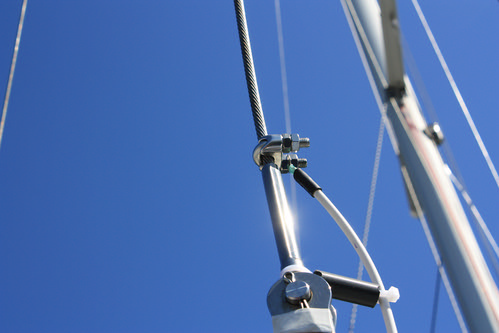
Using a trick I learned from Tom on s/v Warm Rain, I made standoffs to hold the coax away from the grounded portion of the backstay.  These standoffs are simply 2" pieces of 1/2" CPVC water pipe that I got at the hardware store.  I drilled the pipe with a 3/8" drill on 2" centers, and then cut the pieces apart thru the holes.

The standoffs are installed using snap-ties (use black ones - they will last a lot longer in the UV from the sun) going around both the coax and the stay, and passing thru the inside of the standoffs.  This is one of those cases where a picture is worth 1000 words.

73, Bob
WA9BVE/mm2

Monday, April 25, 2011

Music in Margaritaville

Steve and Lulu on s/v Siempre Sabado find a way around the "marine tax" on "marine" speakers:
Been trying to come up with some kind of speakers for out in the cockpit. Something that doesn't cost an arm and a leg (so Bose weatherproof speakers are out) but still sounds pretty good. Speakers have big herkin' magnets in them so a permanent installation anywhere near the compass was out. I've seen very nice installations under the dodger as well as mounted under the boom gallows. But, for one reason or another, none of these really appealed to me. Mostly it was probably because the weather-proof speakers they used are expensive and probably unobtainable in La Paz. I finally came up with a dirt-simple solution.

I bought a pair of 4-way, 250 watt car stereo speakers for the equivalent of about $20 US in one of the many stores in La Paz that carry such things. I cut a couple of holes in a spare lower drop board and mounted the speakers. Ran some wires to a stereo plug near the companionway. Now, when we want music in the cockpit, we just drop the board in place and plug them in. And, since they are pretty much a match for the speakers down below, I didn't have to make a bunch of adjustment to the fader on the stereo to keep one or the other set of speakers from being too loud.

Wasted away again in Margaritaville.....

Monday, March 14, 2011

On being well-grounded

Maintaining a good ground for your SSB without compromising your DC grounding system and thereby causing electrolytic or galvanic corrosion is not easy. But Livia on s/v Estrellita 5.10B makes it look that way. This is a well-thought out solution to that problem
IMG_5456 (1280x853)When we finished our SSB installation in the Polkinghorne Islands, we ran copper foil from our tuner to a single thru-hull. (Pretorien owners, this is the sink drain.) We’ve been checking in on the nets, getting weather and checking email for the last 6 months or so with the copper just draped over the thru hull--->

Our water tanks were already connected to this thru hull with copper wire so we also have our water tanks in the mix.

We decided to start with a minimal ground plane installation and if that didn’t work well enough, add more. We initially did some simple testing of the system and found that we were heard better with both the water tanks and the thru hull than just the thru hull but with just the thru hull we were consistently being heard and connecting to email/weather via winlink.

Even though our tuner (Icom AH-4) has some built in current protection, to further protect from any stray current eating at our thru hull, since the install, we have had to open up the floor panel and manually connect and then remove the foil from the thru hull so it wasn’t touching when we weren’t using the SSB.
Recently, we finished the installation by permanently connecting the foil to the thru hull with some .15 microfarad capacitors as blocks for stray current.

Here we have my tools set out. SV Endless, I promise I am eventually returning your solder iron!

IMG_5467 (1280x853)


Here you can see the pipe cuff that was already installed for the water tank wire (to make contact with the thru hull). Using the screw holes as a template I folded the foil over several times and then drilled holes through the folded copper foil to match.

IMG_5465 (1280x853)IMG_5466 (1280x853)

Finally, I glued the foil to a bit of starboard with a clean gap (no glue or anything bridging the gap) and soldered the capacitors to the foil. My soldering skills remain laughable but so far, everything I’ve soldered still works so I’m calling that a victory.

Here you can see the final installation with the copper wire that goes to a foils strap on our water tanks.

IMG_5471 (1280x853)

We’ve now had a chance to test the installation and it works. The problem with an SSB is that the only way we know how to test it is functionally: it works if people can hear us, if we can hear people and if we can regularly connect to winlink stations. A complication is that propagation makes all contacts vary and recently there were a bunch of solar flares.

Monday, November 8, 2010

Liquid antenna


If there is one thing cruising boats have plenty of, it is sea water.  Everyone uses it as the ground or counterpoise in their antenna systems.  But could you use it to make the antenna too?  Sure!

Monday, November 1, 2010

Standoffish?

One of the problems with running this blog is that I end up with lots things that I see that I need to do. This is another... I have been putting this off for some time - with the current *very* extended sunspot cycle minimum, my interest in radio projects has waned along with the propagation conditions. Carol on s/v Estrellita 5.10b describes here the installation of the wiring between their SSB radio and their insulated backstay:
We use one of the big wires on that run from the deck to the top of our mast as an antenna for our single sideband radio. This wire is called a backstay, and thus the antenna is called a backstay antenna. In order to use the wire that way you have to also have a tuner to tune your wire during SSB usage.

Below, images from an install that I never blogged about. In order to connect the back stay to the tuner I had to cut the co-ax and reinstall it on the tuner. In order to do that I had to solder a PL-259 connector.

Rrrright. So, I don't know how to solder. Many youtube videos and a borrowed solder gun later, I had a not pretty but the good news is that the ugly solder is so far effective because our signal is good. Let's hope it lasts... The work stations, old & new connectors:


I was then able to open our AH-4 tuner and connect the new cord:

The wire was threaded through the ceiling of the aft cabin to the aft port section of the lazarette space and the tuner was installed there. The antenna wire then went from the tuner, through the cockpit combing to the backstay which serves as our antenna.

I used some nylon rod to keep the GTO-15 wire from touching the backstay. I had the brilliant idea to drill holes prior to cutting it so there would be a notch for the wire to sit into. Alas, it turns out the hole I drilled wasn’t really big enough or necessary. Just cutting the rod into 2” sections would have been plenty.


The installation with stainless still wire nut, nylon spacers connected with zip ties, and although you can’t see it the wire terminates in a ring terminal that has been double shrink wrapped at the connection
So, making standoffs for Eolian's antenna connection is now on the list of projects generated from this blog:

Wednesday, September 29, 2010

VHF: handheld vs remote?

If you were in trouble and needed to send a Mayday, which radio would you want to use?  The one in your hand with the 4" antenna 6' above the water (if you're standing) and 5 watts of output power, or the mounted one with a much longer antenna mounted 40-50' above the water and 25 watts of output?

This decision is the one that we examined on Eolian.  See, our VHF is mounted inside, right at the companionway.  This keeps it out of the weather, but accessible.  Well, unless the weather is inclement and we have the companionway closed.  And then there is the fact that Jane just doesn't like to hear the constant chatter on the radio.

So I was considering getting a handheld that I could keep next to me at the helm.  With the volume turned down, I could still hear it, while sparing Jane from the noise.

But then the question above raised itself.

It turns out that our West Marine VHF has the ability to connect (via bluetooth) with a remote speaker/mic that has essentially all the functions of the main unit repeated on its faceplate.

We bought one.  I can keep it back at the helm with me and turn the volume on the main unit all the way down.  And when I transmit, I am using 25 watts, delivered to a 3 foot antenna mounted  65 feet above the water.


Sometimes you can have your cake and eat it too.
Related Posts Plugin for WordPress, Blogger...