More work to my holding tanks! I alluded to some of the benefits of using polyethylene hose for sanitation hose and you can read about it here.[Ed. Note: Solid PVC plumbing pipe (like used in your house) is also recommended as a permanently non-permeating alternative to the garbage sold as "head hose"]
The first thing I did was remove the input hose and fitting, to the holding tank which was located on the side of the tank. Last year, I had relocated the tank air vent to the top and did a temporary block off, of the old side air vent. You can read about that here. That was located just above and to the side of this fitting seen to the left. I used a Dremel and hacksaw to make the cut of the bronze fitting.
I prepped the area to get ready to epoxy glue on a cover over the old fittings. Old paint removed and each opening stuffed with toilet paper so that the glue would not full into the tank. The glue is made from two pot epoxy (slow set) with silica powder/binder added until you get the consistency of thick peanut butter.
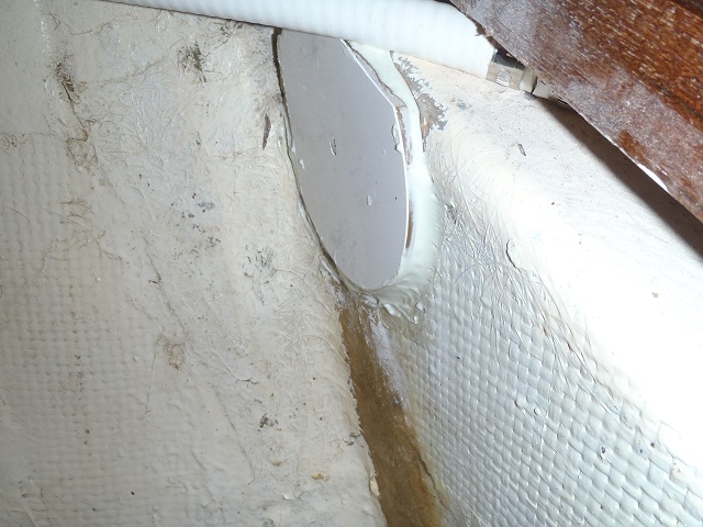
To the left is the finished fibreglass plate epoxied to the tank. This year I decided to use some off cuts of fibreglass which are cut out when the boats are removed from the molds. Typically, they are window cutouts and hatch cutouts which are then discarded. You local fibreglass boat builder will have plenty of these to give away.
In preparation for the top fitting, I found the best location; drilled my hole for the polyethylene through hole; and then sanded the area for gluing the fibreglass plate to the tank.
To the left is the finished fitting. You might notice that the black hose it is attached to is polyethylene pipe.
Polyethylene pipe is NOT as flexible as sanitation hose, so you may have to use elbows etc to get it to go where you want to. You can also use boiling water to get a little more curve from the pipe.
To the right you can see the 25mm polyethylene pipe running down and through the wall where it goes to the macerator pump. The bigger 38mm (inch and a half) pipe runs from the bottom of the tank to the "Y" valve and then the polyethylene pipe continues on to the pump out pump. A diaphragm pump with joker valves each end.
Now the outflow is of poor design and should never come from the bottom of the tank, other than a drop down pipe inside the tank, from the top. This is due to the fact that effluent is always in the outflow pipe which leads to permeation I'm using polyethylene pipe from the bottom of the tank and feel confident, there will be no permeation.
Above you can see I used barrel nuts. This makes presenting pipes up to the fittings real easy. In this case I didn't need to use them, but I had bought them with me, so decided to use them.
To the left you can see the macerator pump with barrel nut fittings at both the inlet and outlet. The outlet has a PVC type which was fitted some time ago. On the other side of the barrel nut, I have a joker valve inside the other half of the PVC barrel nut and then a valve. This is because it is pumping up hill and one day I may need to service.
I have now added a polyethylene barrel nut at the inlet side. Also, but not shown, is a threaded pipe (at the inlet side before the barrel nut), which goes to a valve, before joining up with the 38mm pipe from the toilet bowel. IF the pump needs servicing, I just turn off the valves at either side of the pump; undo the barrel nuts (usually by hand); disconnect power; and pull the pump out. I have a few "boat towels" to mop up the small amount of fluid that will spill.
And let me say, the area smells so much better already. I might even replace the deck pump out hose ( which goes to the "Y" valve. But my wife says, that is just looking for work. Maybe if I get bored sailing?
Listening to "Just Waiting on a Friend" by the Rolling Stones.
Showing posts with label s/v Solace. Show all posts
Showing posts with label s/v Solace. Show all posts
Tuesday, July 9, 2013
Holding Tank Modifications using Polyethylene Pipe
Paul on s/v Solace tackles one of the more unpleasant tasks on a boat - head/holding tank plumbing.


Tuesday, June 18, 2013
New HF/SSB Backstay Offset
Paul on s/v Solace deals with a convenient but inappropriate hand hold...
Solace HF/SSB antenna cable ran down the backstay with a two inch off set as shown in the photo to the left.
The problem was, what to do about the cable as it ran pass the backstay turn buckle. Ordinarily, I might have fashioned something up to keep it tidy, but with the boarding ladder in the middle of the pushpit, people were constantly reaching up and grabbing anything to help themselves get aboard. Mostly they grabbed the back stay and HF cable. Eventually it became loose and pulled out of the deck fitting. (The ladder here is part of the pushpit, but when needed folds down and steps are formed over the railing.) Yes the back stay is right in the middle of the boarding area!
So I came up with another idea. I used two tubes. Pressure PVC pipe; one 50mm and the other 20mm. I made end caps which can be viewed here for the 50mm pipe and some 32mm for some shroud antichafe rollers. (Another project)
The 20mm pipe has some strategically placed holes placed in the tube along one straight line. These were big enough just to fit my pop riveter. The length was assessed to allow the tube to move up the backstay to gain access to the turn buckle. The 20mm pipe was pop riveted to the 50mm pipe.
The back stay was marked for it's present tension and the turnbuckle was then undone.
The first end cap was placed on the back stay and held in place with some self amalgamating tape. A small rope was thread through the 20mm pipe by which later we would draw the HF wire through.
The combined pipe was then placed over the back stay and the top endcap engaged into the 50mm pipe. A small hole was drilled each side and a small SS screw inserted through to engage and hold the top endcap.
The bottom endcap sat on the very bottom part of the turn buckle, just above the swivel. The inside hole here is large because the "T" bolt that makes the bottom part of the turn buckle is larger in diameter than the backstay cable. This bottom end cap does not slide up and down.
The tubing was slide up the back stay and the turn buckle re connected and tensioned. The top wrench, which holds the top swage at the turnbuckle and prevents the backstay from twisting, supports the tubing while tightening the turnbuckle. Once the turnbuckle is tensioned and the split pins applied, the tubing is allowed to to slide over the turnbuckle and engage the lower endcap. The same two holes with screws to secure the endcap were applied to the lower endcap as done for the top endcap.
The HF cable was then threaded through the 20mm tubing and attached appropriately.
Hint. As you undo the HF cable above the backstay isolator, place a small rope around the isolator so that later you can have a companion pull down on the back stay, which will help with re-connecting the turnbuckle. Also, if you buy pressure PVC pipe, it may have black writing on the pipe. A paint thinners on a rag usually wipes this off so you have a nice white tube.
How to stop the pipe from turning? I'm trying some heavy self amalgamating tape at the bottom end, which at the moment has a little give, but seems to hold everything in place. Another method might be to place a bolt through the 50mm pipe and through the turnbuckle openings.
To access the turn buckle again, it is a simple case of talking out the small screws at the bottom endcap and sliding the combined assembly (minus the bottom endcap which stays in place) up the backstay to gain access.
In the photo to the right you can see that there is just enough room to slide the 50mm pipe up the backstay. The HF wire is cable tied to the isolator and gradually moves away from the backstay until it enters the 20mm pipe.
The holes which were made for the pop riveter will later have some 20mm rubber bungs inserted to tidy the whole thing up.


Wednesday, May 29, 2013
Fischer Panda Cooling System Modification
Do you have a Fischer Panda generator? Depending on its age, the following improvement by Paul of s/v Solace will be verrry interesting to you...
Fischer Panda (FP) Generators are now cooled by fresh water and the sea water only passes through the heat exchanger and then out via the exhaust hose. BUT it didn't use to be that way. My FP is around a 2001 model, 5.5KVA. In my FP the cooling is done with sea water, which first goes around the generator casing and then to the heat exchanger, before exiting via the usual exhaust method. The fresh water gets circulated around the engine and through the heat exchanger to get cooled from the seawater that has picked up a little heat from the generator casing.
You can see the heat exchanger situated underneath the generator in the picture below. I consider that poor design and changed my heat exchanger location which you can read about here and also here
To change my cooling system, I figured it was only a case of changing a few hoses over and I could have both my generator casing AND my engine cooled by fresh water and use the raw water only for cooling through the heat exchanger. Read below how I did it...
FP blurb about their water cooling.
First I removed the freshwater hose that went from the engine to the heat exchanger. You can see the fresh water hose coming from the pump (above generator belt) to a metal tube which then does a small bend and goes down and sits just behind the Johnson raw water pump. The removed hose is sitting in front of the pulley.
Next I removed the hose from the raw water pump which goes straight down to a pipe that dives under the motor to the generator casing.
The idea is to swap these two over. Fresh water will now go to the generator casing, and raw water to the heat exchanger.
In the picture to the right, you will now notice, the pipe that sat under the raw water pump has been moved to the right a little and hooked up with the fresh water pipe coming down from the fresh water pump. (pump not seen). I had to cut about two inches (50mm) off the pipe so that a hose will connect.
I had this 20mm pipe (in picture to the left) made for this change over.
In the picture to the right, you can just make out the curved pipe as it is now attached to the raw water pump and the pipe continues to the heat exchanger underneath the pulley.
Now, at the heat exchanger. the pipe that use to be fresh water is now raw water and should be connected to the raw water input at the heat exchanger.... AND the raw water input hose at the heat exchanger is now fresh water. Just swap the two over.
So, lets follow the path of the fresh water first.
From the fresh water pump, it goes down beside the crank pulley and dives under the motor to the generator casing. From the generator casing, the fresh water goes to the heat exchanger to be cooled and then returned to the engine at the header tank. From the header tank, it gets circulated around the engine and repeats the cycle.
Now the raw water.... It leaves the raw water pump and goes straight to the heat exchanger; picks up the heat and then exits via the exhaust. Just like the new FP's.
Finale hookup with generator belt back on.
BUT, that's not the end of it. You might imagine that the generator casing may have some internal salt deposits. So, I first ran the engine up with fresh water to temperature and then after cooling down some, drained that water away. I then did another run up using a product called "Salt-X". I mixed with water as per directions and repeated the draining of the fluid after cooling down some. This Salt-X is a produce for removing salt deposits in outboard engines and should be available in most marine Chandler stores. Finally, I did another fresh water run up and emptied that too, before using a ethylene glycol "antifreeze/antiboil" product. I'll change that in about 9 months time as well; to make sure all salts that remained have left the cooling system.
We also have a fresh water flush system for both our engine and Genset. As we get ready to shut them down for a while, we open a valve to our fresh water tank and close the sea cock. We let the engine run for a minute or two and this then flushes out the seawater from the heat exchanger. Thus prolonging the life of the heat exchanger. Then, after shuting down the motor, it is important to close that fresh water valve; otherwise, the next time you open the sea cock, it can back pressure to the fresh water and ruin your tank supply. It usually only happens once. :-D
All up, it took about 2 hours and a ten dollar item to complete. Antifreeze and Salt-X were extra costs; but you should replace you antifreeze once a year anyway. It's mostly for the anti corrosion properties that we use it.The engine actually runs slightly cooler, and with a trip up to the tropics soon, will be beneficial.


Thursday, May 23, 2013
Small Clothes Drying
Paul on s/v Solace has an easy answer for drying small clothing items - made from items you probably already have on board:
Some years ago, we were in the Pacific islands and my wife bought at a market, a round plastic hanger with multiple clothes pegs hanging off it. She used this to hang her underwear and socks from, both outside and inside the boat. Well, eventually the plastic thing broke and she lamented the loss of her "never, never holder". She says, "underwear should never be seen hanging off life lines or even a clothes line".
So I set about one evening to duplicate what she had before. I used two garden irrigation "T's and some reinforced hose to make the basic shape. I drilled through the plastic hose and placed short sections of about 3mm line through; held from slipping through, with just an overhand knot on top. Next I drilled the pegs and did a similar knot to hold the pegs. Finally I made a bridle in the middle cross piece and placed a cheap small carabiner at the center of the bridle by which to hang the contraption.
About 1 hour to make and less than $10


Tuesday, May 7, 2013
Chain Stripper Modification
Paul on s/v Solace makes a significant improvement in his windlass by redesigning the chain stripper. This is inspirational to me (since Eolian doesn't have a stripper on her windlass); perhaps it will be for you too:
Bent stripper compared to new stripper
Last year I had a guest on board who was trying to be helpful and undertake some of the chores on the boat. He was going through the anchoring process and while anchoring, I (he) found a deficiency in my capstan while easing out chain as one puts on the snubber.
Normally, when bringing in the chain with the capstan, a stripper is in place to ensure the chain comes off the capstan and goes down the Hawse pipe. Otherwise, it can get caught in the gypsy (wildcat in the USA) and wind up the chain around itself. Easing chain out, say when anchoring, the weight of the chain is usually sufficient to take the chain of the capstan gypsy. But in my case, my guest was not aware of the potential issue and as he eased the chain out while holding tension on the snubber line, the chain stayed in the gypsy and bent the chain stripper on the opposing side. You can see the bent stainless stripper above.
Plastic compared to SS
We were in the middle of "nowhere" and there was no way I could straighten that stainless. So what to do? I used one of my wife's "polyplastic" chopping boards and cut it up to make a plastic, but temporary chain stripper. While getting everything ready, including a cardboard template, I decided to design it so it was able to strip the chain whether it was coming in, or going out. I used both hacksaw and Dremel for fashioning the plastic stripper and the thing worked so well, it stayed on for the whole cruising season (6 months). I improved the cardboard cut out a little and had a piece of 6mm stainless laser cut when I went home.
Plastic stripper in place
New SS stripper to replace plastic in place


Thursday, March 7, 2013
Square cut to Radiator Hose
Today, Paul on s/v Solace shows us a masterful way to cleanly cut heavy hose:
Sometimes we need to cut radiator type hose with a nice square end. Some of you know how hard that can be with the hose unsupported and cut with a hacksaw. Here’s how we do it. BUT, don't do this if the hose has a metal spiral inside. Your saw blade won't like it.
Take the hose and find a suitable piece of dowel to insert into the hose. It helps to have a firm fit and if your piece of dowel is slightly over sized, use a belt sander to take the end of the dowel down to a slight taper until it fits snugly into the end.
From my pictures you can see two hoses; one fitting inside the other. It was important for me to not only get both hoses cut square at the ends, but to also have both hoses cut to the same length.
Once the dowel was placed in the end. A line was marked and we used a table saw to cut the hose. Be careful not to cut fingers! Leaving the dowel in place in the end of the hose, we turned it over and repeated the process at the other end.
If you don’t happen to have a table saw, here’s another technique you can use. Once your dowel is placed, take a square piece of paper, and roll it around the hose so that one edge comes around and lines up with the same edge as it is rolled over the hose. This is to ensure the proposed cut line is square to the hose. Slide to desired position and with the paper firm and edge lined up, scribe a pencil mark around the hose on the paper edge. Remove the paper, and now proceed with a hacksaw to cut the hose to the line; rotating the hose as the hacksaw cuts into the wooden dowel. This is a better technique if the hose has the metal spiral "spring" inside it. The hacksaw will cut through that OK.
Thanks to Paul Gooch for his tips


Tuesday, October 30, 2012
It may not seem like the right time of year to do a project regarding bug screens... in the Northern hemisphere. But Paul on s/v Solace is located in the Southern hemisphere, where this a good and proper project for this time of year - Making replacement bug screens:
[Editor's note: Not sure that the 3M 4000 - or any adhesive for that matter - would stick to polyethylene]
I have two port holes in the side of the cockpit well (near the floor), which we keep open all the time. We place in the port holes, these snap in bug screens; but as you can see, from the picture to the left, some of the plastic has broken off. It is also broken in a couple of other places not visible in the photo. These bug screens are 1985 vintage and have just deteriorated through use and I suspect UV damage. Also, these sit around shoe level when sitting in the cockpit, and occasionally get popped out by an accidental heel kick.
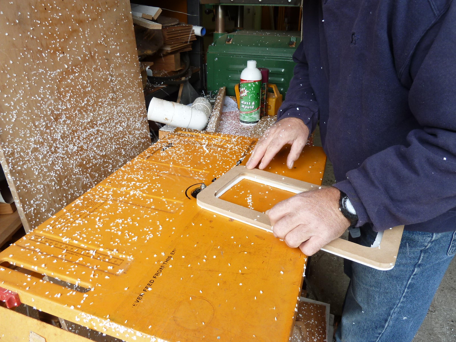
Wooden Template
In reconstructing these, I first made a wooden template suitable for a router. I used MDF (medium density fibreboard). Next I procured some PVC board, which when doubling the thickness of the PVC board, was just a few millimeters thicker than my old bug screen. I used PVC, but could just as easily have worked with Polyethylene plastic board.
Next I cut out of the PVC board, four rough finished frames which were about 5-10mm wider than my template. You might notice that my template has a wider surface than the original bug screen. This was to give it some added strength and make it easier to place the bug mesh between the two PVC cutouts.
Routering
I used double sided sellotape to secure the template to the rough cutouts and then routed the remainder of the PVC off to the finished template. Each one was done in turn.
Then because my template wasn't exactly symmetrical I matched two pairs so that all corners lined up perfectly.
Mesh glued and trimmed
I lay one side of my PVC cutout down and placed a small bead of 3M 4000 deck caulking compound in the centre of the flat surface. Then I placed my bug screen mesh (Nylon I think) over the top off this, then spread the 4000 over the mesh so that it was in the middle and not near the edges, and sat level with the mesh and not proud. Final tension was then applied to the mesh and it was allowed to set up. This was to act as a "glue" so I could the trim the mesh about 1mm in from the outer edge after it had set up.
4000 applied before 2nd side attached
Next application of 4000 was applied in a thin layer over the mesh, but not approaching the inside edge by about 5mm. If the 4000 is squeezed out to the inside and over the mesh, the job looks "ugly" and once set is hard to remove from the mesh without damaging it.
Glass over top for glue to set
Finally the other side was applied, being careful that both PVC cutouts lined up perfectly. The PVC was pressed down from the inside edge to the outside, squeezing out any excess 4000. A plate of glass was applied over the two pieces and allowed to set up.
After it has set up, a sharp craft knife was used to trim the excess off, on the outside edge.
Finished product
The finished product to the left. It's both flexible and hardy. Should last several years. But, if you need to change the mesh, just slip a blade between the two sections to break the bond. Clean up and repeat the process for new mesh.
What am I going to secure it with in the port hole? Probably "blue tack"; but one could use a double sided foam tape, like they use to secure mirrors on walls.
Don't try to do the gluing in one step with the mesh. I tried and it was very difficult to have both PVC pieces line up perfectly. Also when trimming the mesh off, you could still see the mesh on the outer edge and it looked "ugly". A much better finish, if you glue the mesh to one piece first; have it set up, and trim the mesh back from the out edge. Then, when trimming the final outer edge of 4000 is done, a nice white finish is all you see. So, in essence, what you see here is a bug screen that has had the mesh replaced once because I didn't do it right first time. Cost $30 for the PVC 1 square meter sheet; and $7 for the mesh.


Tuesday, July 5, 2011
Bug Screen for Companion Way Hatch
It seems that this is the time of year when folks are thinking about straining the bugs from the air they direct below for ventilation. Here's a solution that Paul on s/v Solace came up with:
In addition to our new bug screens placed on the hatches inside the boat, we came up with an idea for the companionway hatch that is easy, cheap and functionally easy to apply and use.
My wife sourced curtain mesh from a haberdashery (that is a curtain/fabric store) along with weighted line used to weight the bottom of curtains. She sewed a bungy into the mesh which sits along the top of the companionway slide and we had convenient power out sockets on which to locate the bungy hooks.
From the bungy, all around the edge, was sewn the weighted line/rope that we also bought; to give the mesh the ability to form to the companion way entrance.
Egress is now easy to just brush aside the mesh and then throw the weighted edge back over the companion way once you have made your way through.
From inside


Monday, June 13, 2011
Upgrade to less power
Paul on s/v Solace instructs us on replacing fluorescents with LEDs.
Nicely done! And it does retain the original character - an important consideration for boats.
Original non working light
We have had a fluorescent light inverter/ballast fail on us and had a number of options to choose from. My first thought was to change the whole light structure to a more modern fitting, but was eventually convinced by my wife that to do so, was taking from the character of the boat. A new light could have been procured from the USA, but I was still looking for a better light that uses less power. Here's what I did to keep both the original light fixture, but upgrade the light that consumes less power.
I removed the light fixture and purchased a LED strip light that would fit the light fitting.
New LED lights ready to be fitted.
I removed the the two ends for the florescent tube to make way for the new LED strip. I applied double sided tape used to attach mirrors to walls etc, to secure the LED strip and the switch, to the old light fitting. It was important to keep the original switch as it contained the electronics which helps with the LED strip to function efficiently.
Removal of the florescent ends needed
New LED light fitted.
The refitted unit was wired so that the original switch on the side was the main means of turning the unit on . The inline switch supplied with the LED strip was left on and fitted inside the light fixture. My wife has declared the light very good, and now wants me to convert another light so she can do fine needle work.
Finished light. Time to complete was about 40 minutes and the LED strip procured locally in New Zealand for about $37USD


Wednesday, June 1, 2011
Cover the ugly Electric Winch
Paul on s/v Solace shows off his carpentry skills by making a below-decks cover for his electric windless, with some difficult corners...
We had a new electric winch installed as we moved to a roller furling boom. The electric winch was the same size as the old two speed, but the electrics protruded through the aft bedroom ceiling. Also, we had a ceiling light at the same location as to where the electric motor protruded through. My only choice was to make an enclosure for the electric motor and I took the time to also add a new low profile light to the cover box.
The cover box was made from Rimu, and while not matching the Cherry wood interior was close. We will have a Cherry wood one made when we can easily source the wood. You will note the angle at one of the corners on the cover box. This was placed on the cover to allow the door to the head, to swing from it's usual locked open position to the closed position. You can just see the opening door surround, to the left of the cover box. The light was placed and some strips of wood secured to the ceiling to give the cover something to screw to. For my wife and I, it is not a head banger and is no lower than the tops of the door openings. The Electric winch is a joy!


Wednesday, May 25, 2011
When you're hot...
Rather than just replacing it when it failed, Paul on s/v Solace hot-rodded his BBQ grill:
Some of us have BBQ's on our boats, which after time, seem to not perform as well when new, and in my case had an annoying feature. Mine progressively produced less heat and had grill bars which allowed fluids to drip into a "catch tray" but often overflowed and dripped on my deck. In the end I couldn't bbq any way, because the heat from the element just seemed to die.
Original Magma BBQ
With the cost of new BBQ's being very expensive, I decided to rebuild the unit myself and hopefully save some money.
So, first I "gutted" the heating element from the BBQ. Then I purchased a 5.5KW [that's 18,700 BTU/hr -Ed], two ring propane burner. This I purchased in New Zealand for about $30USD from a hardware store, but I remember that these where very common in the islands at most of their hardware stores. They use them to put large pots on to cook with.
Two ring burner
Next I cut the end of the BBQ with a Dremel to open up to allow the valves of the burner to protrude through and allow gas hookup.
Control valves for gas. Comes with burner.
Next I purchased a BBQ plate with it's own raised ridges and channels for fluid to drain away from the meat. The BBQ plate was a generic plate and wasn't quite the right size for my Magma. I used a metal cutting wheel and cut to size. But to keep all fluids produced while BBQing, I welded a metal strip along where I had cut. The BBQ plate came with handles at the sides, which proved to be a bonus for handling the plate. Plate cost $15USD from the BBQ Factory Store.
Finally, I purchased a small 3KG propane tank along with a new regulator and hose. The tank had a bracket made for it so that it could be mounted on the railing close to the BBQ.
BBQ plate in place. Metal strip at front.
Finally, to "season" the plate, a coating of oil, was rubbed into the plate and the plate "cooked" to allow for the burn in. It is now important to heat the plate and then turn down the heat, because it actually gets too hot and burns off the seasoning. Cooking steaks is now a great success, with the steaks being seared on the plate with ease, rather than a slow broiling which use to happen. All guests have declared my BBQ steaks to be wonderfully cooked.
All fluids seem to "evaporate", including fats, so it is important to spray periodically with oil to keep the "seasoning" up. Otherwise the plate will just turn rusty.
Cost for the BBQ mods. $45USD and about a days work looking in the stores and the workshop work. A small piece of scrap mild steel strip I had lying around and a welding machine was needed in addition to the dremel and steel cutting wheel on the angle grinder.
Bottle to BBQ


Friday, May 20, 2011
You know you worry about it...
Paul on s/v Solace has a nifty way to monitor the temperature in his refrigerator and freezer.
We have recently changed our method (compressors and evaporator plates) to our fridge and freezer. We wanted a reliable method to monitor the temperatures with out extra wiring. We have tried the manual thermometer, but found them less than satisfactory due to having to open up the boxes to read the temperature. We came across these wireless "indoor, outdoor temperature monitors" on ebay for a reasonable cost. This model has one LED monitor, with two sender units. It is able to monitor two temperatures at a time. We put one sensor in each box, and the LED monitor in the galley in a convenient place. They have been going two years with only one battery change. They measure about 2.75 inches square each.

Monday, May 16, 2011
Endless hot water
Now there's something we'd all like to have... Paul on s/v Solace will have it now, even at anchor!
I am curious to find out how the propane usage will work out in practice.One thing lead to another with these boat projects. This blog is about linking three boat projects, and each one is worthy of it's own post. But for now, I'll give a precise of the events.
Firstly, in the shower cubicle of the boat, I had a cupboard with a large 12 gallon hot water tank that I wanted to replace with a washing machine. So I set about removing the HW tank and then installing the washing machine. Because the doors were only 18 inches wide, the WM had to be disassembled to get through the door and then reassembled in-situ. This may become another blog at some time.
Now, because I had removed the HW tank and our only method of heating water, I then set about installing a califont, or probably better known as a "heat as you go, propane water heating unit". This was a unit sold in New Zealand, but I have seen similar units sold in RV World in the USA. The igniter is powered by two "D" size batteries, and is small enough to install in boats and RV's.
I installed the unit under the aft vanity unit on a bulkhead. I have a means of varying the temperature output and have placed some blue masking tape for the shower temperature so that we don't need to use the mixer tap to get the temperature right. The ducting is 4 feet in length and vents to the bilge. Heat at the end of the 4 foot ducting is almost nil, and one can hold your hand over it easily. I saw many units installed on other boats with out the ducting to outside, and as others have said, "it's no worse than running the stove". Propane and co2 monitors are a safety measure. Now we have hot water on tap with no need to run the generator to supply power to the old HW tank.
Finally, when installing the propane califont, I had to install a propane hose to the unit. Initially, I "Teed" into the existing propane line with the one propane cut off switch to be used to supply both the califont and the stove. This however proved to be less than satisfactory, because the califont would remove some of the gas from the stove line while it was in use. This then made igniting the stove burners, a little more time consuming as we had to wait for the gas to flow back through the line to the stove.
The solution was to use another solenoid and regulator for the new califont and "Tee" in both solenoid/regulators to that "Tee". Each solenoid has it's own on/off switch.
New Brass T to Propane Tank
We also plumbed a hot water line to the aft of the boat so that we can have hot showers on the aft deck. We also think we will use less propane, than heating a kettle of hot water on the stove to do the dishes. I'll comment on that as data comes to hand.
The "T" also allows us to carry a spare propane tank to swap to when running out on the tank in use.


Subscribe to:
Posts (Atom)


