About a month after buying Rubigale, and with a boat full of crew, we were ready to leave the fuel dock after a day of sailing. After pumping out I went to start the engine, turned the key, and nothing. Not even a click. I knew nothing about engines-zero, zip. I could find the alternator and the dipstick. My knowledge of cars surpassed that of boats only because I knew where to put in windsheild wiper fluid. I didn’t know how I was going to get back to my slip and had a half dozen people that needed to go home. My boat mentor J had his own boat full of crew and couldn’t help at the moment. Fortunately, T lives aboard a few docks away, and after I fished out a mystery set of wires with clips that I had found in the bowels of weird boat storage (had this happened before?), he jumpstarted the boat by connecting the battery to the start switch.
Success!
I thought the crew would disappear as soon as we were back to the slip, but J and T started troubleshooting the starter and half of the people stayed, rapt with the process. I didn’t understand much of what I was hearing, but I was mesmerized by the problem solving. I photographed where to connect the wife to the starter just in case. Final diagnosis, probably a bad starter switch because there were loose connections and a little corrosion. J showed up with a new starter the next day and showed me how to put it in. It was much easier than I had expected and I photographed that as well. As a bonus, he connected a new engine hour meter to the switch so I could keep track of hours since the previous meter had died at just under 4000 hours at some unknown point in the past. Everything seemed to work great and I put it away in my mind as a solved issue.
Showing posts with label electrical. Show all posts
Showing posts with label electrical. Show all posts
Tuesday, June 20, 2017
Starting A Boat With A Paperclip
This isn't a project per se... well actually it is, but the most important part of this post is the successful trouble shooting of a problem. And yes, it does invoke MacGyver-ism. Read along with Dana on s/v Rubigale, as she deals with a motor that suddenly refuses to start...


Tuesday, August 23, 2016
Rumpus Room Media Center
Michael & Melissa on s/v Galapagos turn their V-berth into a media center. (And I must confess that it was this post which convinced me to get a label maker.)
In previous posts we have reported on our progress in updating the V-berth. With a new cushion and upholstery, the space is really comfortable and has become like a second salon. We will use the V-berth as a guest cabin when company is aboard but when it is just the two of us, we call this the space the Rumpus Room.
One of the more decadent projects I have been planning is to have a TV and DVD player on the boat. We watch more movies on the boat than we ever do at home and it is has become a bit of a ritual to save up a season of some show to binge watch when we are out on a cruise. For example, we have season six of Downton Abbey unopened and ready for our Memorial Day South sound trip.
In the past, we have used a laptop to watch movies which is okay but not optimal. The speakers aren’t too great and since the battery life on our laptops is pathetic, we have to plug in to the inverter to keep the juice flowing. It works but the whole setup seemed a little cheesy.
So, for some time I have been ruminating on how I would install a small entertainment center on the boat. With the Rumpus Room all but complete, now seemed like a good time to stop thinking and start installing. Alas, as with every other boat project, installing one thing means you must drill, move, re organize and generally tear the boat apart, twice.
One of the most important criteria for designing this system was to have it be entirely powered from the 12 volt system. There are a few small TV and TV/DVD combos which are set up for 12 volt. Long Haul truckers use them and there are some marine grade systems as well. But the units I found seemed really expensive relative to their size.
So last year (I ruminate a long time) I was looking at a TV or computer monitor and noticed that it had an AC to DC power supply (commonly referred to as a brick). So, just like your laptop, you plug the brick into an AC outlet but the TV is actually running on DC. However just because the TV uses DC does not mean it will work with the 12 volt system on your boat but the seed was planted and more research ensued.
Finally, after a bit of googling, I went to Best Buy and looked at the smaller Insignia brand LED TVs. Most of these use a AC to DC power supply and one, the Insignia 24 inch LED TV. actually uses 12 volts. Be aware that Best Buy sells a few 24 inch TVs in this size and brand. This model was the only one I found in the store that used a 12 volt power supply. If you want to attract attention at Best Buy, start moving their TVs around and unplugging the power supplies so you can read the voltage and current values for the output. Also it is quite fun to try and explain a project like this to someone that is not entirely sure that TVs even use electricity.
$140!
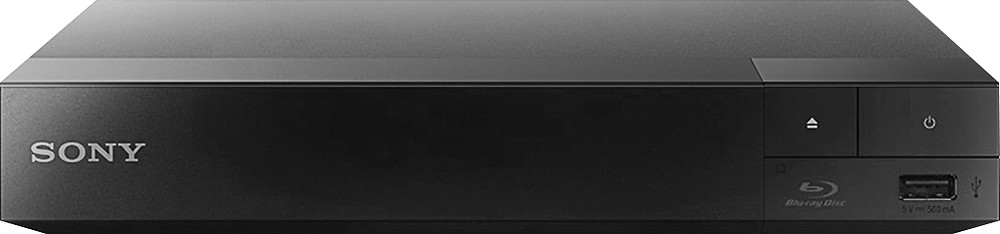
With a TV secured, I also wanted a DVD player that could also run off the 12 Volt system. This was quite a bit easier since the players are small and I could look at the power supplies without too much trouble. I ended up buying a Sony BDP-S3700 for $80. You can buy a cheaper DVD player that will work well on 12 volts for about half the price but this unit is WiFi capable. At home, the only TV we ever watch is via NetFlix or Amazon. I doubt we will be doing much streaming of video away from the marina but we might stream from a networked hard drive at some point.
Sony BDP-S3700
$80
I wanted to mount the TV on the bulkhead both to keep it out of the way and to improve the viewing angle. For this task, I bought the $40 Rocket Fish Full Motion TV mount.
I was and still am a bit worried about the security of this mount and will continue to monitor this. The TV only weighs 6 pounds but in a bouncy sea way the stress could be higher than the attachment points were designed to stand. I will also install a bungy cord to hold the TV snugly against the bulkhead when not in use.
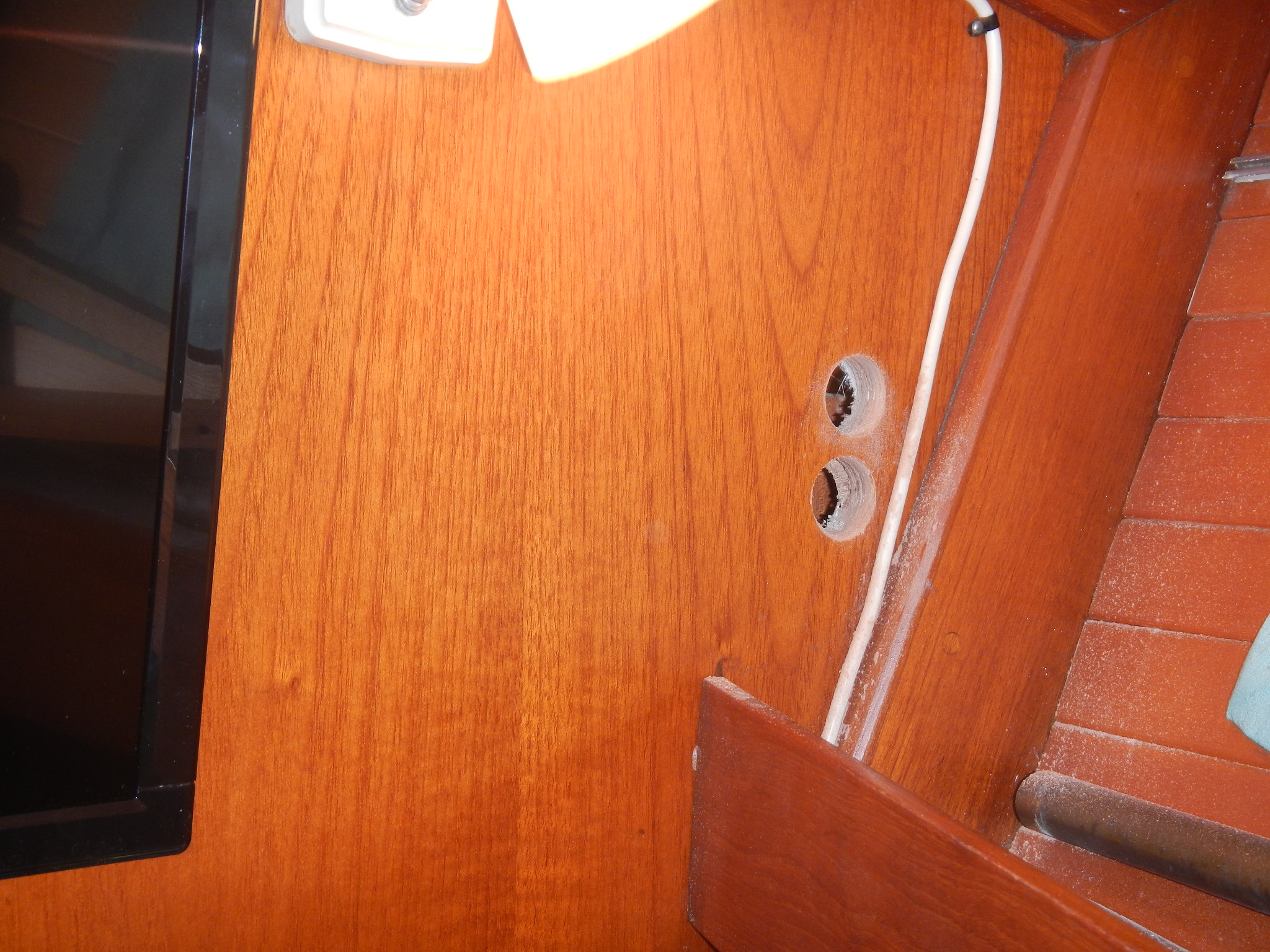
So, with the main components secured, I still needed to run wiring to the bulkhead and create outlets for the the TV and DVD player. That’s where tearing the boat apart comes in. I ran 30 feet of 12 gauge marine wire through the forward head, salon, galley and into the DC distribution panel.
Probably the moment of truth to this whole project is when I cut the DC connector off of the bricks for the TV and DVD player. You are committed when you willfully destroy part of the equipment you just paid good money for. I could have bought adapters for each of the electronics and made new wiring harnesses for them but I don’t intend to use the TV anywhere but on the boat. I did keep the bricks and could always splice the wires back together.
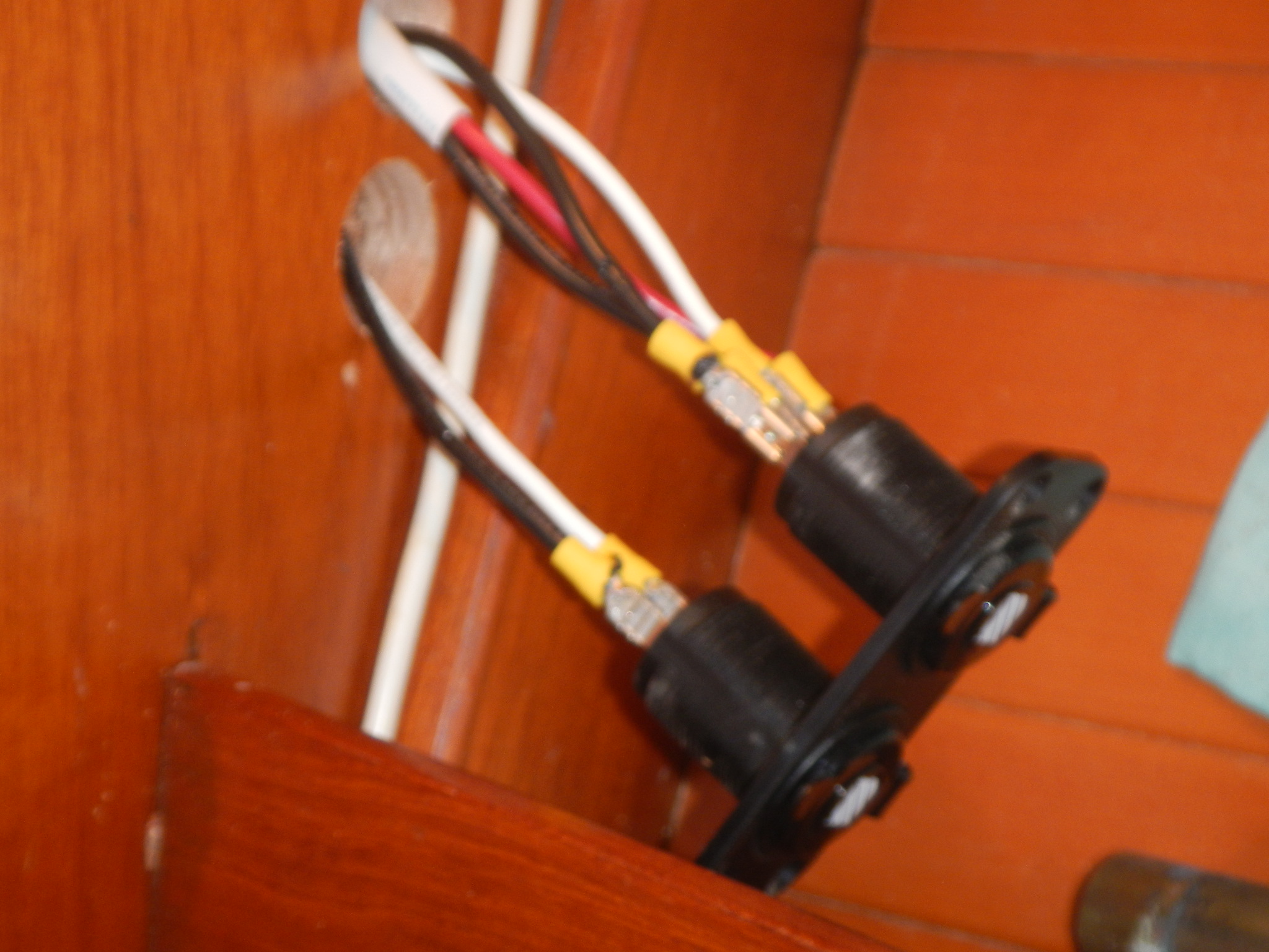
After cutting the wires and checking the polarity three times, I soldered the the wires onto the fused DC Accessory plugs I picked up for the purpose. And Finally the moment of truth.
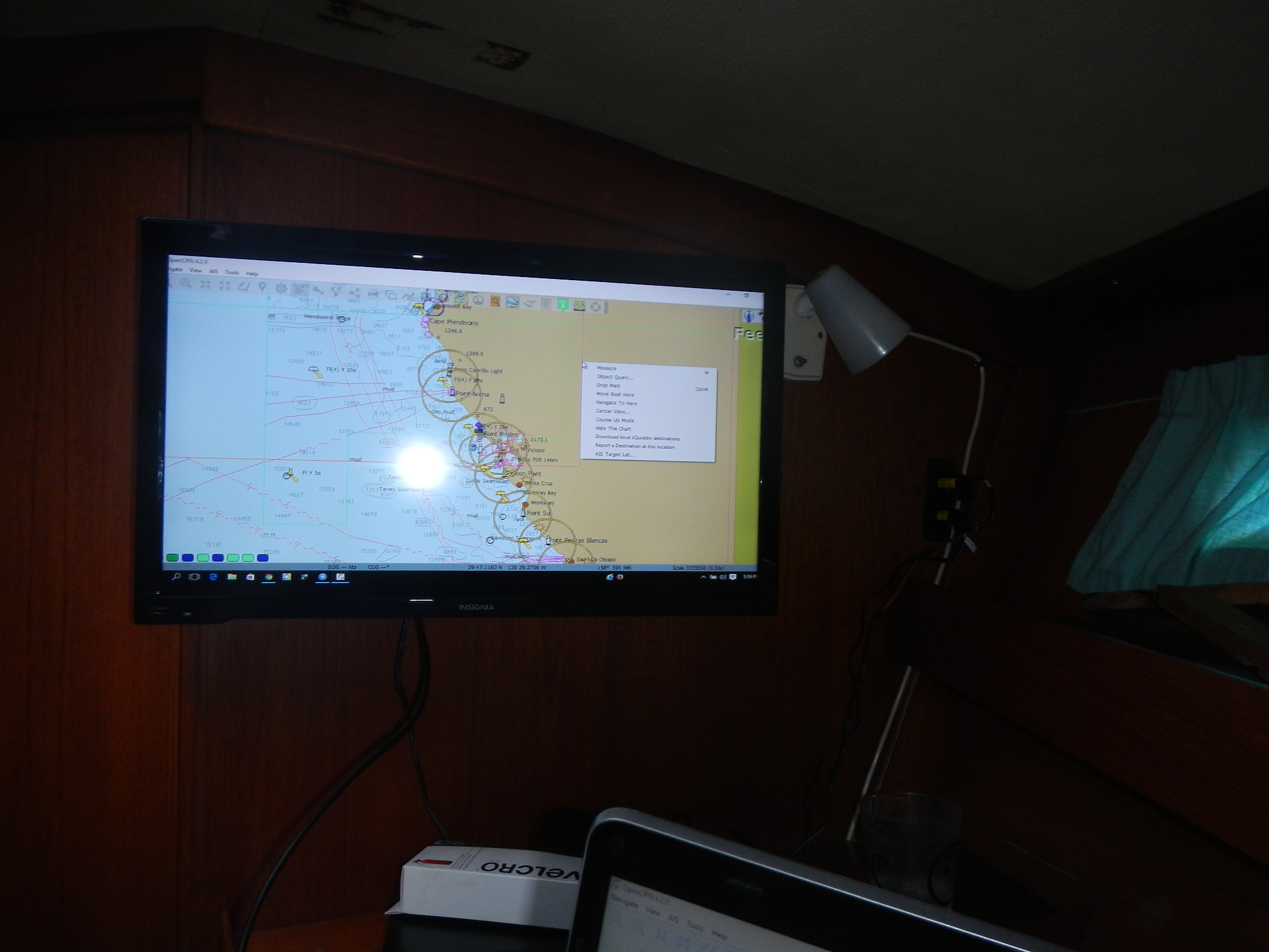
I have Open CPN on my laptop and it displayed beautifully on the TV. I could see using this display for planning a day’s journey with Melissa.
Both units worked perfectly! After a little fussing, I was even able to stream Netflx with the DVD player. The audio quality is quite good for such an inexpensive TV and the Rocket Fish mount makes it easy adjust the viewing angle. I think that will be particularly important if we use the TV as a computer monitor.
With the WiFi enabled DVD player, we can stream Netflix if a signal can be found. Foss Harbor marina recently added a really nice WiFi system to our dock and it worked beautifully.
The power supplies that came with the TV and DVD player both had an open voltage of about 15.5 volts DC, well over the charging voltage that any of the charging sources on Galapagos provide. Still I will probably just unplug these devices when not in use to be on the safe side. A low voltage condition might cause problems as well and I will have to monitor that as we go.
So far, I am quite pleased with how well this project turned out. I love not having to turn on the inverter and trying to make the tinny laptop speakers loud enough. All in all, a nice addition to our Rumpus Room.


Tuesday, July 5, 2016
Where Do The Buses Go?
Jeff and Anne continue their full refit of s/v Pilgrim. Living around and on boats for a long time, with a solid engineering understanding of what makes a good one (and a bad one...) has really informed Jeff's work on the boat. If you'd like to see how a boat *should* be wired, here's a glimpse into the work. But you'll need to read the rest of Jeff's posts to get the full picture.
In September 2015, I posted to updates about converting Pilgrim’s 12V Positive Bus into a custom ANL Fuse Block...
Over the winter we installed the custom 12V positive fuse block and the corresponding 12V negative bus.
For those out there asking what is an electrical bus? An electrical bus is simply a distribution or consolidation point along the path the electricity takes to the device the user wants to power. If the electrical wires are like train tracks snaking around a country side then the electrical buses are the train depots that allow people on the main line to switch trains and take side trains to smaller communities and vice-versa on their return trip. The fuses ensure that the outbound trains (positive wires leading away from the batteries) to not become dangerously over crowded with passengers.
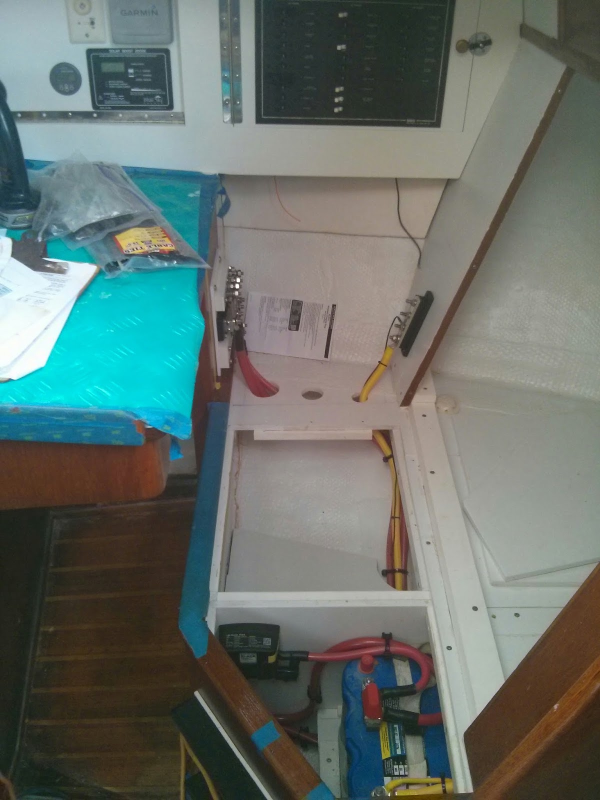
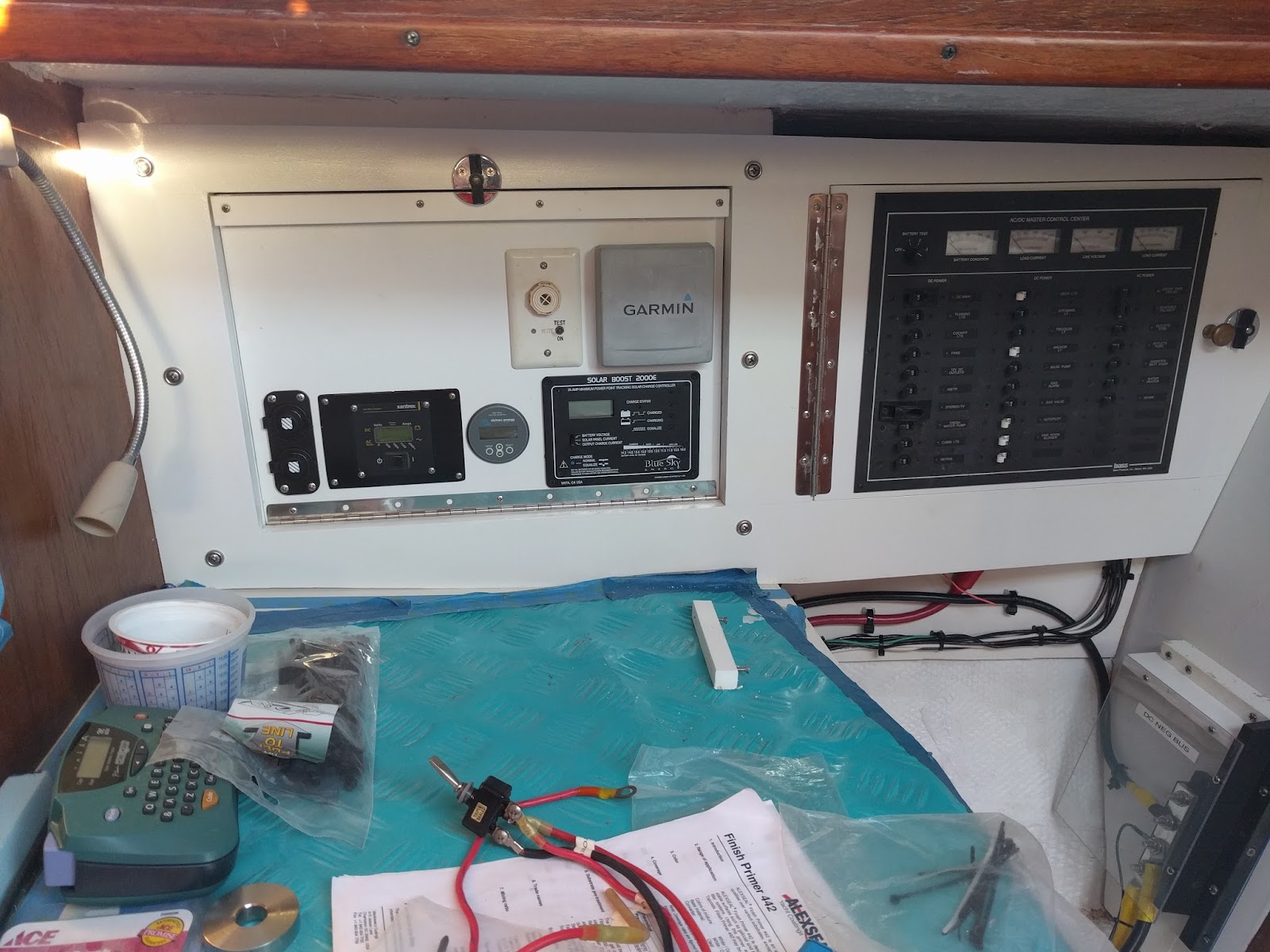
Consolidating the electrical wiring components around the nav station is a priority for us.. Installing the buses below the electrical panel offered a centralized location that provided plenty of room for the large gauge wire runs.
Pilgrim's 12V Primary Buses installed below the electrical panel.
Early on in our refit we chose to eliminate the M382’s quarterberth in favor of additional storage space. Eliminating the berth allowed us to create a seat back at the nav station. The middle two panels of the seat back are removable. The outboard seat back panel is fixed. We installed the negative bus on the fixed vertical seat back panel and the positive fuse block / bus opposite along the original nav station structure.
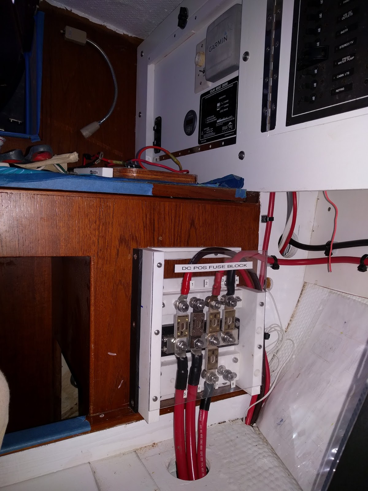
To prevent accidental shorts in a busy area, I fabricated starboard and plexiglass covers for the two buses.
12V Primary Positive Bus / Fuse Block with plexiglass cover.
12V Negative Bus at lower right in image.
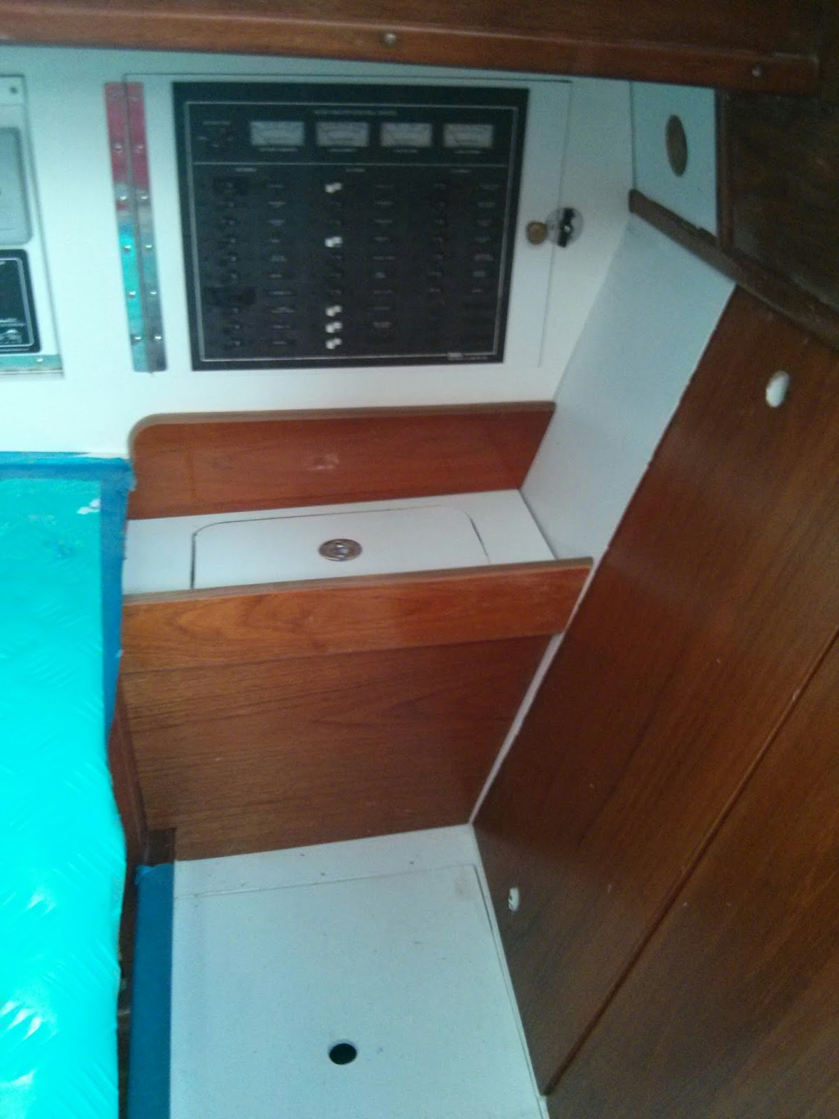
The final step was to create a functional armrest to house the unsightly wiring runs and electrical components.
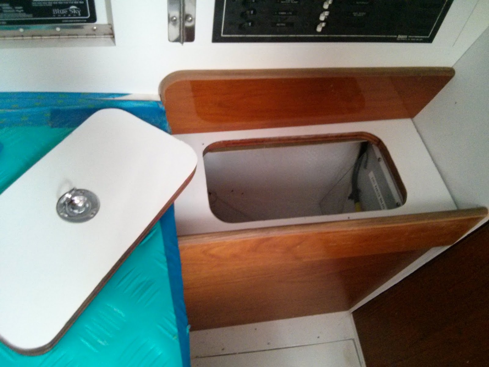
New arm rest at nav station. The armrest has a removable panel to allow for storage and quick access to the fuses.
Removable panel in arm rest allows for easy access to fuses and storage space.
If additional access is necessary for repairs or upgrades the armrest is designed to easily remove the vertical wood panel via four screws.
Additional photos and notes can be found in our on-line albums.
Re-wiring Pilgrim Photo Album
Nav Station Refit Photo Album
Will post more updates on Pilgrim’s electrical system soon.
Tuesday, May 17, 2016
Exposed Wiring
Over at Sail Delmarva< Drew cleverly fabricates a cover for some exposed wiring...
This exposed solenoid always bothered me. Non-AYBC compliant, non-USCG compliant, and a short looking to happen, the backside of this anchor windlass breaker has high-amperage exposed terminals.
I fabricated this simple cover from 0.09-inch FRP (the same materials I used for the window covers. Cut by score-and -snap, trim with disk sander, fillet corners with Epoxy + colloidal silica, finish with orbital sander and paint. In stead of screws (holes would show), attach with 3M Dual Lock.
The finished product looks factory. I think I will be using a lot of Dual Lock during the AC installation.


Tuesday, March 29, 2016
Crimping Lugs onto Large Gauge Electrical Wires
First of all, thank you, all of you, for your patience and for your well
wishes. They are very much appreciated! The neck surgery was to
correct a nerve pinch in my cervical spine that was causing me to lose
the use of my right hand. Recovery is proceeding apace.
OK, enough of that.
Aboard s/v Pilgrim, Jeff & Anne continue their refit. Today they show us how to make up terminals on heavy gauge wire... I do encourage you to check out the comments on the original post - there are some useful pointers in there to suitable tools for crimping.
OK, enough of that.
Aboard s/v Pilgrim, Jeff & Anne continue their refit. Today they show us how to make up terminals on heavy gauge wire... I do encourage you to check out the comments on the original post - there are some useful pointers in there to suitable tools for crimping.
Our recent installation of Pilgrim’s primary 12V DC wiring required the numerous large gauge, 4 to 00, electrical wires. If you’re wondering which is the larger wire a 4 or 00, then check out our previous post – Let’s Talk Marine Wire, October 18, 2015.
Large gauge wire runs at electrical panel and starter battery.
Large gauge wire runs at house battery bank.
Here are a few things I picked up about crimping lugs onto large gauge wires.
Happiness is having the right tools for the job at hand. The key for installing wire terminals on large gauge wire is having the proper crimping tool. Unfortunately appropriately sized, quality crimpers are expensive and rarely part of the DIY sailor’s quiver of tools. Fortunately I am currently able to borrow a great crimping tool with dies for crimping 6ga through 4/0ga.
If anyone out can recommend a source for purchasing a quality pair of crimpers functional on 6 to 2/0 wire, then please share the info in the comments.
Tools and materials: Clockwise from the top - heat gun, medium duty wire cutters (blue handle), large gauge wire crimper with multiple dies, 2/0 x 5/16 post lugs, heat shrink tubing, 2/0 wire.
Heavy duty wire cutter and a sharpie style marker are essential tools missing from the image above.
I’m not certain if there is a technical difference between lugs and ring terminals. In my vernacular ring terminals are used with smaller gauge wire and typically have heat shrink insulation already installed. Lugs are typically non-insulated fittings for larger wire. If anyone out there has a different definition / delineation, then please let me know.
Ring terminals and lugs need to be sized to the correct gauge of wire and to the correct post diameter. In the image below both lugs are for 2/0 wire. The lug on the right fits a 3/8” post and the one on the left fits a ¼” post.
22ga to 8ga insulated ring terminals on left. 6ga to 2/0ga lugs on right.
Two 2/0ga lugs with holes for different size posts.
Avoid aluminum when purchasing wire connectors. Like marine wire all terminals and lugs should be tinned copper.
I’ve found my medium duty wire cutters will realistically work on wire up to around 1 gauge. 0 through 4/0 wire will require large cable cutters. Sailing vessels should be carrying large cable cutters to deal with wire rigging in the event of a dismasting (See our C’est la Vie post: Dis-masted – Part 2 if you doubt the necessity of having large cable cutters aboard.) Cutting 4/0 wire is easy with the large cable cutters.
Once the wire is cut to the proper length, slide a section of heat shrink tubing for each lug to be installed onto the wire. Sliding the heat shrink over the wire at this point will aid in avoiding any fraying of the wire once the insulation is removed. Next, using the lug as a guide mark the amount of insulation to be stripped off the end of the wire.
The medium duty wire cutters are my tool of choice for stripping wiring larger than 10 gauge.
Stripping 2/0 wire using medium sized wire cutter.
Apply gentle pressure to the handles while rotating the cutters around the wire. I prefer to rotate back and forth through 180 degrees. Rotating through 360 degrees is ergonomically awkward and often results in a spiral cut on the insulation. Stop the motion when you begin to feel the strands of copper against the edge of the cutters. Knowing when to stop cutting and how much pressure to apply comes with practice.
Once the insulation is gone, I move directly to installing the lug. Expediency at this step will aid in avoiding any fraying of the small stands of copper wire.
Crimping a lug on a 2/0 battery cable.
Once the crimping is completed, I give the lug a through visual quality inspection. If satisfied with the connection, then slide the heat shrink tubing over the junction and let the heat gun do the rest.
Numerous 2/0ga battery wires in Pilgrim's house battery bank.
Happy Crimping!


Tuesday, January 26, 2016
Fabricating a DIY ANL Fuse Block
Jeff and Anne continue with their thorough refit of s/v Pilgrim. Here they tackle the fusing of the primary wires in the 12V electrical system. And they do it right. Jeff made this as two separate posts, I have collapsed them into one here.
Pilgrim’s progress is crawling towards the installation of the primary DC electrical wiring. The primary wiring components are:
- Battery Bank(s)
- Large gauge, high amperage wires connecting primary components
- Shunts to allow for the installation of battery monitors
- Switches for directing or cycling on/off the flow of power through primary wiring & components
- Bus Bars to make multiple wire connections in which all the wires are on a common circuit.
- Terminal blocks to make multiple wire connections in which the wires are on separate circuits.
- Terminal posts for making connections in which the wire(s) are on separate circuits.
- Fuses to protect the wiring and components from excessive amperage.
We purchased a BlueSea 600A Power Bar to serve as the primary distribution point for the DC positive wiring. The wiring leading from the positive bus will be fused at the battery box. A few of the other wire runs will need to be fused proximal to the bus bar.
Simple Diagram of Pilgrim's Primary 12V DC+ Distribution Bus
We are installing ANL Fuses for Pilgrim’s primary wiring system. Rather than purchase individual ANL fuse holders for each circuit requiring a fuse “downstream” of the positive bus, we are fabricating our own ANL Fuse Block.
Materials used to create DIY fuse block clockwise from top: Starboard, BlueSea Bus, ANL fuses, 5/16" Stainless Steel Fasteners.
Our fuse block will utilize a ¼” thick Starboard™ base to mount the BlueSea Bus adjacent to a DIY terminal block. The gap between the bus and the terminal block will be set up to accommodate ANL Fuses. ConFUSED yet? Hang in there pictures are worth a thousand words.
Our DIY terminal block will consist of ¾” Starboard™ with 5/16” countersink machine screws as studs.
Laying out the spacing for the 5/16" countersunk holes.
The holes in the ¾” Starboard™ are positioned to match the alignment of the BlueSea bus bar. The holes are drilled and countersunk to fit the 5/16” machine screws.
Inserting the 5/16" machine screws in the starboard block.
The screws are inserted from the underside of the block with the threaded portion of the screw exposed on the topside. A washer followed by two nuts jammed against one another secure the screws to the Starboard™ block.
Inserting a couple ANL Fuses between the new block and the prefab bus ensured proper positioning when we mounting the two pieces on the base.
Completed fuse block sans the wires and one fuse.
The bus and the terminal block are held in position by #10 counter sink machine screws capped with lock nuts. The base extends ¾” beyond the assembly on each side. This excess base will provides area for mounting screws.
When installed in Pilgrim the fuse block will have large gauge wires and/or an ANL fuse attached to each post.
Mock up of wiring attached to fuse block (still missing one fuse.
The image above is a mock-up of the future installation aboard Pilgrim. From the top down…
- The upper wire feeds power from the engine alternator when the engine is running.
- The second wire (currently missing an ANL fuse) runs to a BlueSea Systems Automatic Charging Relay (ACR). The ACR charges the starter battery when voltage in the circuit is between a preset range. The ACR also isolates the house bank during engine starting.
- The third wire feeds power to our battery & bilge pump management panel. Here is a link to our previous post: Installing the New Battery & Bilge Pump Management Panel – June 28, 2015
- The lower wire (labeled “B”) runs to the house bank of batteries. This wire run is fused proximal to the battery bank.
After reviewing the installation manuals for the BlueSky 2000E PV Solar Charge Booster, the AirX Wind Generator, and the ProNautic 12.40 Battery Charger, Pilgrim’s DC+ wiring schematic continued to evolve. The DIY ANL Fuse Holder (see previous post) needed to double in capacity.
Original Fuse Block Design:
Updated Fuse Block Design:
I disassembled the original fuse block; doubled the size of the base; and added a second row of terminals.
Expanded DIY ANL Fuse Block
The missing fuse feeds the Battery & Bilge Pump Management Panel. We are still figuring out the correct size fuse for this circuit.
Eager to check out Pilgrim’s DC wiring schematics? I do plan on posting the wiring diagrams after a few “outside consultants” review my plans.


Tuesday, October 27, 2015
Low-Cost Depth Finder
Over aboard s/v Cay of Sea, Rick thinks about depth sounders, and replaces his. He keeps the original transducer tho, making this an easy project.
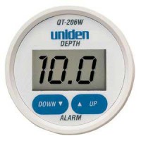
Before our July cruise, I installed the Hawkeye Depth Finder Model #D10D because my previous low-dollar depth finder (Uniden QT 206W) had failed. I’ve had a good opportunity now to compare the performance of both, and can definitely recommend the Hawkeye over the Uniden.
It seems that it is possible to pay up to $500 for a large format “sailboat” depth finder that mounts on the bulkhead. However, the availability of high-dollar stand-alone units is dropping off due to the popularity of consolidated multifunction displays for gps/chart plotter/depth finder/radar displays. And as I’ve looked at the market recently, I’ve noticed what seems to be greater selection among models and makers in the budget depth finder realm. I think makers of marine gear are understanding that the market for high-dollar gear has out priced the budget boaters, and they are now offering more products in the $100-$150 range, which is where I live as well. Don’t mistake this as altruistic behavior on the part of marine gear makers – I’m sure they are more motivated to not leave money on the table by ignoring this large group of boaters.
Regardless, the Uniden model represented a poor value with respect to construction and performance. I had this unit installed on my boat for about four years. After the first year, the display began to suffer from UV and weather-related damage, although it still functioned. The plastic display became frosty, the printed controls lost their readability, having faded in the sun. Finally, the display window cracked, which allowed moisture to enter the unit and make it unserviceable.
Performance-wise, it was inconsistent at best, but I must say that whenever I absolutely needed to know the depth when approaching shoal waters, it gave me the right information. This may in part be due to my choice of installation. I installed the transducer inside the hull without drilling a hole, and I didn’t glue it to the hull with epoxy – rather, I bedded it in a blob of silicone. I am confident this degraded its performance to some degree. It would never give much in formation in waters deeper than 50 feet, and often in choppy conditions it would return error readings, I assume due to the amount of air passing underneath its location just behind the vee-berth, or the inability of the processor to keep up with excessive motion as found in choppy conditions. When that area was ventilated by air bubbles, I feel sure the device had a more difficult time determining depth. Additionally, it featured a gain, or sensitivity adjustment on the back side, which was extraordinarily touchy.
By comparison, the Hawkeye, while still mostly plastic, features a glass screen. While vulnerable to impact damage, it is nearly impervious to effects of UV radiation, which means that the screen will always be readable. Additionally, it comes with a protective cover which will shield the unit from the sun during the many days and weeks when the typical boat is not in use. I did not install the new transducer that was included in the purchase. Instead, I determine through reading the spec sheet, that both Uniden and Hawkeye used the same frequency and wattage transducer. Not installing a transducer spared me a lot of trouble and effort with the installation. I was also curious how the unit would perform with the old transducer.
So at about the same price point (approx. $100 for each) the Hawkeye is a much better value than the Uniden. I feel more confident with this unit on board than I have with any other brand during our ownership of Cay of Sea – and early on, we had a “legacy” Datamarine large-format (read expensive) depth gauge.

Tuesday, October 20, 2015
Transforming Current
Please welcome new contributors Sean and Louise, who live aboard their 52 foot one-off steel motor vessel, m/v Odyssey. For their first contribution, Sean offers a project which provides insight into marine electrics - a subject that can never have too much light cast upon it:
I'm perpetually behind on projects here, which I think is a condition of living on a boat, or perhaps just a condition of modernity. So I've been taking the time, on otherwise idle days at anchor, to whittle away at the list. I'm also perpetually behind on blogging some of the major projects I've already done, such as the great 24-volt conversion project that I've been promising to write up for over a year now.
In an effort to keep the backlog from growing, I thought I'd use some of the time to write up one of the most recent, considering weather has pinned us down here for at least another day or so. As with so many projects, this one has been on the list for a long time, but has bubbled to the top because recent events on board increased the urgency. I am talking here about fixing the main AC panel ammeter that tells us how much power we are drawing from shore or generator systems.
The ammeter, in this case, is part of the Blue Seas AC/DC circuit breaker panel built into the helm console, which is original to the boat and has been there, according to the photo record, since it was originally finished under the first owner's watch. While large and swoopy-looking and "custom" labeled, this breaker panel is actually an off-the-shelf item available in the Blue Seas catalog. The labels come with it on a big sheet of commonly-used circuit names, for customization by the installer.
Main AC ammeter (left) and selector switch.
As such the ammeters are actually pre-installed and pre-wired on the panel. The DC ammeter is hard-wired and measures all the current passing through the main DC breaker on the panel, while the AC ammeter is wired, along with the AC voltmeter, through a built-in switch that allows it to be switched from one AC leg to the other.
This is all well and good, but in this configuration it has, as far as I can tell, never, ever been able to measure all the current the boat is drawing on either leg. That's because there are some large AC loads that do not actually pass through the panel on the helm.
When we got the boat, the big culprit in this regard was the washer/dryer. It's located in the engine room and is the only 240-volt appliance on the boat. When the automatic transfer switch (ATS) was added during the last owner's stewardship, the electricians split the feed to that appliance off right at the ATS, running it through a separate tiny panel with a two-pole breaker for the washer/dryer and another single-pole breaker that supplied the engine room exhaust fan. Any current being used by those items was thus not included in the totals shown on the helm ammeter.
The engine room fan was moved off this arrangement early on, because wired in this way it could only be operated on shore or generator power. We don't typically run the generator under way, which is exactly when we need the exhaust fan, and so I moved it to a circuit connected to the inverter.
Having the enormous load of the dryer invisible to the ammeter was problem enough in itself. We often tripped the shore power breaker when using the dryer, until we learned just how much (or little) other load we could have on the system at the same time. We had to go by feel, guessing at the amount the dryer was using at any given moment, subtracting that number from the 50-amp shore supply, and keeping everything else under the remainder based on the panel ammeter.
The problem grew much worse when I completed the aforementioned great 24-volt conversion project. That involved, among other things, a new inverter/charger, which was best wired with a 120/240-volt, four-wire circuit, thus loading both legs of the input power, in contrast to its predecessor which was a 120-volt-only, three-wire load and was supplied by a circuit on the main helm AC panel.
The "new" main panel, in the engine room, a 120/240-volt 8-space "main lug" QO-series panel. Two-pole breakers feed the inverter/charger and washer/dryer, while two single-pole breakers feed the two sides of the former main panel at the helm.
The helm panel has no provision for 240-volt circuits (it's arranged as two separate 120-volt panels), which is probably why the washer/dryer was not wired to it, and why I could not wire the new inverter/charger to it either. Moreover, wiring such a big load through the helm meant the power would pass right by the load in the engine room on its way to the helm, through the panel, and then all the way back again, adding cable, weight, heat, and voltage drop.
So now we have two of the largest consumers on the boat -- the dryer and the battery charger -- that do not register on the helm ammeter. Even with the higher 67-amp capacity of the generator circuit, we still occasionally trip a main breaker, and this problem is just getting worse now that we are running air conditioning more often. And if we want to deliberately load the generator right to its limit, to reduce wet-stacking, we have no good way to monitor our progress toward that end.
The simple answer to all of this is to move the input for the panel ammeter down to the engine room, immediately after the transfer switch, so that it can see the full draw of everything on the boat. Easily said, but a lot of work to actually do.
AC current is measured with a device known as a "current transformer" (CT). Unlike most transformers you might encounter in a typical electrical system, which transform one voltage to another, a current transformer actually transforms one current to another, proportional, current. In the case of our ammeter, it's a 1,000-to-one ratio: a 50-amp current passing through the main feed is transformed into a 50-milliamp current into the meter, while, say, a 12-amp current would result in a 12-milliamp meter input. The meter pegs at 50 milliamps, but the dial is marked from zero to 50 amps.
Physically a CT is a toroidal coil, with the current-carrying conductor to be measured passing through it. It picks up the magnitude of the measured current by induction. The CTs in the Blue Seas panel are very small, just big enough to go around a 6-gauge wire with a bit of room to spare, making them easy to fit into the tight space for which the panel is designed. That also made them ideal for installing in the tight space of our new main electrical panel in the engine room.
One of the two Blue Seas CTs, still installed in the old panel. The CTs that Blue Seas uses have their pair of lead wires molded in. Blue Seas has soldered the other ends of the leads to the selector switch. I cut the leads at about their midpoints. To extend these down to the engine room I needed about 35' or so of two-pair wire, but all I had on hand was some 4-pair CAT-5 communications cable. While I would not use untinned, coarse-strand cable like this for any critical application on a boat, for the meter it would suffice. I used two pair for each CT to minimize the resistance. At least the fine twist of CAT-5 will also minimize inductive interference in the signal.
CT relocated to new main panel in the engine room. The zip tie just keeps it from sliding on the wire.
After moving the CTs and splicing the wiring at each end, we fired up the genny for a test. While I was concerned that such a long run of meter wiring might impact the accuracy, a quick check with my clamp-on meter revealed that the helm meter is spot-on. We now have an accurate reading of the full draw on both legs up to a maximium of 50 amps, which is the limit when we are on shore power.
The generator is a 16kW unit, however, which means it is theoretically capable of producing 67 amps, and in practice has a 70-amp main breaker. Consequently, when running on the generator the 50-amp ammeter can and does peg occasionally, particularly on the leg carrying the battery charger, which by itself can draw up to 30 amps. For the time being, we avoid leaving the meter connected when running above 50 amps (the selector switch has an "off" position).
I'm not too worried about running the CTs at 30% above their 50-mA rating, as these are minute amounts of current. But the meter itself could be damaged long-term, and besides, we'd like to know exactly how much we are drawing even when we go above 50 amps. So I will probably devise a shunt that can be switched in when on the generator to divide the reading in half. I'll need to experiment to determine the meter's internal resistance in order to size the shunt.
We almost never trip breakers when running on the generator, which is large enough to run almost everything on the boat simultaneously unless we are running the dryer, which we try to run mostly on shore power anyway. So the meter is most useful in managing the more limited shore power feed, and for that, the 50-amp full-scale reading is perfect.


Tuesday, September 22, 2015
No More Neon
This post originally appeared on Windborne in Puget Sound
In 1978, when Eolian was built, LED's were an expensive novelty. Therefore the lamps on her control panel that indicate the presence of shore power, generator power, and correct AC polarity were the tried and true neon lamps.
A neon lamp is a stupid simple device - a glass envelope filled with low-pressure neon and containing two closely-spaced metal pins. It will light up when presented with 110V, drawing a vanishingly small current (400 uA). But they don't last forever. Eventually they grow dim and begin to flicker. And then finally they go out.
I had replaced the shore power neon lamp in the power panel in our first year of stewardship of Eolian. It's the one that is lit the most, and therefore was the first to fail. And, coincidentally, it's the only one that is somewhat easy to get at on the inside of the panel.
After 15 years, it had failed again.
But now LEDs are common and cheap. I found these, designed for direct connection to 110V, on the Internet for a couple of bucks apiece. Installing them was not easy. The back side of the power panel is quite crowded, and it was apparent that the original lamps came with the panel and had been installed before any of the wiring.
I did the deed at anchor, with the generator and inverter off, so there was no 110V present to worry about. I got them in, but I had to take an Excedrin afterwards to deal with the cramps in my shoulder.
Hopefully they will last longer than the neon ones.
I'll let you know in 15 years.
 |
| Yup, AC polarity is correct |
In 1978, when Eolian was built, LED's were an expensive novelty. Therefore the lamps on her control panel that indicate the presence of shore power, generator power, and correct AC polarity were the tried and true neon lamps.
A neon lamp is a stupid simple device - a glass envelope filled with low-pressure neon and containing two closely-spaced metal pins. It will light up when presented with 110V, drawing a vanishingly small current (400 uA). But they don't last forever. Eventually they grow dim and begin to flicker. And then finally they go out.
I had replaced the shore power neon lamp in the power panel in our first year of stewardship of Eolian. It's the one that is lit the most, and therefore was the first to fail. And, coincidentally, it's the only one that is somewhat easy to get at on the inside of the panel.
After 15 years, it had failed again.
But now LEDs are common and cheap. I found these, designed for direct connection to 110V, on the Internet for a couple of bucks apiece. Installing them was not easy. The back side of the power panel is quite crowded, and it was apparent that the original lamps came with the panel and had been installed before any of the wiring.
I did the deed at anchor, with the generator and inverter off, so there was no 110V present to worry about. I got them in, but I had to take an Excedrin afterwards to deal with the cramps in my shoulder.
Hopefully they will last longer than the neon ones.
I'll let you know in 15 years.
Tuesday, May 19, 2015
Steaming Lamp/Deck Lamp Guard
Over aboard s/v Cay of Sea, Rick avoids paying the marine tax by fabricating his own guard for his steaming lamp:
Okay, I’ll admit that I don’t know exactly what to call this thing, but I know what I want it to do – what I hope it will do, if it is robust enough to do so. First, some background:
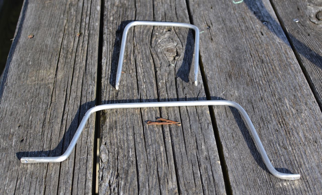
Two years ago my deck lamp was knocked out of the fixture, including the lens (I think), by an errant halyard slap in high winds. Well, that wouldn’t be too bad, except that I had just replaced it. It’s one of those two-pronged halogen 20 watt lamps, and they are sort of pricey. Not only that, but I hate going up the mast. Now I’d have to do it again! There has to be a better system. I imagined at the point, that some sort of cage of rods would be an adequate protection against another halyard slap. I’ve seen them on other boats, but I’ve never seen one advertised for sale, so I have no idea of availability or price. But how hard can it be to make something like that? While the mast is still horizontal and I have time before launch, I thought I would give it a try. I should be able to come up with something.
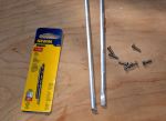
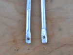
I went to the hardware store today to look for materials, and came home with 36″ of 1/8″ aluminum rod, eight stainless #6 screws, and a drill bit and tap for #6 screws.
Back in the shop I cut the rod in half and flattened the ends of the two pieces with a 3-pound maul against my closed vice, then drilled holes in the ends for the screws. I used a mill file to clean up the sharp edges.
Back at the boat, I estimated the lengths, attachments points, and the approximate locations of the bends. Without a vice on site, I found convenient places to capture one end of the rod while bending the appropriate place against a leverage point. This is what I came up with:
I managed to get one leg of the smaller piece longer than the other. Doesn’t really make a difference. It attached to the mast without complication, but it does bother me that the legs are not exactly the same length. . .
I located the larger piece on the mast first and marked the attachment points. Using a steel punch, I made a small divot point in the mast at each screw hole location to get a clean start with the drill bit. Carefully locating the drill bit, I used significant pressure and slow speed to start the hole (the mast is a curved section, remember? Hard to drill a hole in something like that without having the bit walk all over the place). Each hole started and finished cleanly. I cut threads into each hole with the tap, then ran a screw into it to ensure clean threads. If you never tapped a hole, it’s an interesting process. Everything is extremely low tech, except for the tap itself – which is hardened steel, tapered at the point, with the cutting threads beginning immediately. I use a small adjustable wrench to turn the tap a quarter turn at a time as I guide it into the hole as perfectly perpendicular as possible. It’s helpful to back the tap out a quarter turn after every complete turn or so, to clean the metal debris from the cutting threads.
I marked, drilled, and tapped for the second (port-starboard) piece next, then mounted both pieces with screws well bedded in TefGel. TefGel is a non-conductive corrosion inhibitor, and it allows me to use stainless fasteners into an aluminum mast without threat of galvanic corrosion. Every place I’ve used it on the mast has been completely corrosion-free since I refit the mast eight years ago.
In case you’re wondering, sheet metal screws, or self-tapping screws are an inappropriate fastener for this application. In fact, anything screwed into the mast should be done with machine screws. They have much finer thread than self-tapping screws, and hold much more securely. I like what Don Casey says about sheet metal screws in a mast: “I’ve never seen a sheet metal mast . . . ”
Point taken.
After fitting both pieces, I linked them with a zip tie, reasoning that having them linked together would give them a bit more rigidity (4 attachment points, vs 2).
Here’s the finished product:
Nice rounded features should allow halyards to slide right off and past the light. Cost? About $10, including the drill bit/tap set. We’ll see if it does what I hope it will. Although the rod is quite bend-resistant, the fasteners could be the weak point. As long as they don’t get wobbly, I think it will be fine. They are torqued as tight a I dare and seem quite sturdy, although it may be smart to install lock washers under the fastener heads. Any opinions out there about this?


Subscribe to:
Posts (Atom)


