Here is a link to… Sun Cover for Dodger Windows – Part 1
Due to the irregular shape of the side windows and some challenging topography where the dodger meets the cockpit combing, I decided to start the install with the center panel. I’ve installed snaps on past projects, but for this project I had a new tool in the arsenal… the Snaprite by Sailrite.
inaugural use of the snaprite system Specialized dies transform a rivet gun into a tool for placing and installing snaps. The sailrite instructionalvideo explains this system far better than I could hope to do in text.
Front panel installed now onto the sides As with any tool there is a learning curve. I broke multiple mandrels attempting to set a single snap stud (base) and still was unable to achieve a proper roll over on the eyelet barrel. Achieving a secure set on the studs was so frustrating that I reverted to the old system of using a die and punch by the time I began work on the side panels . The Snaprite tool did shine when used for locating and setting the snap button & socket into the new sun covers. This tool really took the guess work out of locating the proper place to install the top portion of the snap.
Once both the center and side panels were installed, I realized that the long gap where the center panel met the side panes could catch enough air to generate noisy flapping.
the intersection of the two panels did not provide a suitable area to mount a snap stud The dodger did not have a site for attaching snaps in this area. I return home to the sewing machine with the covers in tow. If the site was unsuitable for a snap, perhaps a velco?
using webbing an velcro to secure the panels at the intersection A few inches of of velcro and some 1” flat webbing saved the day.Not only to the cover’s protect the widows from UV damage, but they provide a nice bit of privacy when in a crowed anchorage or at the dock.
the view from the cockpit with the sun covers installed Creating the dodger sun covers is the first project fully completed on SV Pilgrim!
As with most of our projects we have created a photo album – Dodger Sun Covers – Winter 2014, that contains additional images. All our albums can also found in the links section, right side pane of our website – M382Pilgrim.blogspot.com
Showing posts with label s/v C'est la Vie. Show all posts
Showing posts with label s/v C'est la Vie. Show all posts
Tuesday, April 15, 2014
Sun Cover for Dodger Windows - Part 2
Last week, we followed Jeff and Anne as they created new a sun cover for the dodger on s/v Pilgrim, but the project was not complete. This is the rest of the story...


Wednesday, April 9, 2014
Sun Cover for Dodger Windows
Jeff and Anne have a new boat, s/v Pilgrim! To provide continuity here, you can follow this link to their previous boat's projects. Today, they give us some instruction in canvas work and stitching with their Sailrite LSZ-1...
The quality of Pilgrim’s dodger stood out on my first visit to the vessel. The clarity of the strataglass windows is remarkable when compared to other vessels in our boat search.
Jeff on the foredeck while prepping Pilgrim for transport in the Sandusky Harbor Marina Now that we own Pilgrim and plan to take her south, protecting her wonderful windows from year round, low latitude UV damage is a high priority on the project list. Fabricating a removable sun cover for the windows seems like the best solution.
We feared using royal blue that matches the existing dodger fabric would generate too much heat in warmer climates. Our choice of colors… a contrasting white UV resistant fabric.
Using the center window panel to create a rough cut out of the fabric. Initially I attempted to measure out the pattern. This worked well to estimate the amount of fabric for the job, but proved too inaccurate for creating a pattern. After one false start that resulted in a permanent blue line across the lower section of the front panel, I tossed aside the tape measure and simply outlined the panels to create a rough cut out of the covers. With the fabric atop the panels I was able to fine tune the dimensions of the cover and thus skipped creating a pattern.
I placed the fabric atop the panel to fine tune the shape of the cover. The side panels were created via an identical process.
using the side panels as pattern for the cover In the design phase, I decided to use edge binding rather the hemming the covers. Using red or green 1” webbing as binding tape for the edges allows for easily identification of the port & starboard side panels. Additionally, I used red and green on the corresponding sides of the center panel to assist with orienting it to the dodger. White binding tape was used for the top and bottom edges of the center panel.
adding a second row of stitching to the binding tape on the port side panel To provide additional longevity to the covers the edge binding is double stitched in place.
The covers were now ready for the installation of snaps that will affix them to the dodger. I felt the snap placement would be more accurate if completed with the windows installed in the dodger. Time to load up the project and head out to the boat…


Thursday, August 15, 2013
New LED Running Lights for the Bow
The failure of a lite bulb in the running lites aboard s/v C'est la Vie led to Jeff and Anne upgrading to LED lites. And then there's that 5200...
Last fall during our migration from North Carolina to Florida our port forward running light burned out. I purchased what I thought to be the correct replacement bulb, but the new bulb was either too large, too high a wattage, or both. The result was a melted lens and damaged socket (I do realize this could have been much worse.)[Editor's note: C'est la Vie was dismasted on July 5 off the Frying Pan Shoals. Jeff and Anne are fine, and C'est la Vie was able to motor under her own power to a safe harbor, where whe is currently hauled out. You can read more about this here, here, here, and here. There are some important lessons to be learned from this - I encourage you to read Jeff's account of the event.]
Through a bit of internet searching I found some tear drop shaped led replacements made by SeaSense and purchased them last December.
The new LED running lights
I went back to seek a link for the lights we purchased and they have vanished from the SeaSense website, but can be found on ebay. This is unfortunate since the fixtures were an accurate enough match to C'est la Vie's old lights that the replacement was relatively easy, but I'm skipping over the removal of the old lights.
A copious ring of ling cured 5200 surrounding the old light fixture
The person installing the existing lights did not hold back on the 5200. I feared the lights may be difficult to remove without marring the exterior hull paint. For this reason, I began my extraction efforts sweating away in the anchor locker scraping, prying, grunting, and cursing at the elastic gobs of 5200.
using Anne's paddle board as a work platform to access the running lights
When additional efforts in the anchor locker grew futile, I launched Anne's paddle board and used it as a work platform from which to launch my external attack on the bedded lights. After one lap around the fixtures with a razor knife the fixture parted ways with the hull. Success. The starboard side came free with similar effort.
Successful extraction of old fixture. Now back to scraping 5200.
Some additional work went into removing the surface 5200. When test fitting the new lights, I was elated to discover that the port side matched down to the pilot holes. The starboard side took a bit of sanding and drilling out the pilot holes to correct minor misalignment.
Anne crawled into the anchor locker and I remained on the board as we worked together to bolt in place the new fixtures. Rather that replacing the 5200, we used butyl tape to bed the new lights.
Successful test of the new bow running lights.
Shortly after installing the fixtures afternoon thunderstorms stalled our efforts. I returned this morning and wired the new lights. C'est la Vie is now legal and two fixtures closer to 100% LED. I think the deck spot light and the engine compartment lights are the only incandescent bulbs remaining on the boat.


Tuesday, July 16, 2013
Running Wires for Solar Panels & Wifi Antenna
Last week, we featured Jeff and Anne's installation of new solar panels on their boat. Now that the panels are installed, they still need to be wired into s/v C'est la Vie's electrical system...
Pulling wires though small openings and running wires along tubes pretty much describes my afternoon Wires from the new solar panels now snake over the bimini, along the stern rails, and thorough the deck via a new through deck fitting installed starboard side aft.[Editor's note: C'est la Vie was dismasted on July 5 off the Frying Pan Shoals. Jeff and Anne are fine, and C'est la Vie was able to motor under her own power to a safe harbor, where whe is currently hauled out. You can read more about this here, here, here, and here. There are some important lessons to be learned from this - I encourage you to read Jeff's account of the event.]
We purchased a WirieAP which serves as a wifi antenna and creates a wireless network for the boat. Our decision to go with the Wirie was based on a Practical Sailor review and additional internet research. I must admit the the fact that the creators of the device and owners of the company are live aboard sailors won them some favor as well.
One #10 wire from each panel now runs down along
the starboard stern railing and through the deck.
The unit is self contained in a waterproof box. The only cabling is a wire for power. The unit is sold as a 12V DC system, but a 120V AC adapter is included in the box. The unit also includes a mounting bracket for 1" to 2" poles. Experimenting with different installations on C'est la Vie, we elected to bolt it through the angle brace on the wind generator tower. This does place the antenna close to the pole, but once again life of a sailboat is a series of compromises (or is that true of life in general?)
the new WireAP mounted on the
stern wind generator tower
With the antenna mounted, I returned to running wires. Fortunately a through hull fitting already existed for the Wirie cables.
Pulling all the wires below decks forced me to excavate the contents of both the lazurette and the starboard side cockpit locker.
The cockpit quickly became an obstacle course / work area.
work zone or obstacle course?
As light began to fade from the sky and the hungry Everglades bugs began to take over, both the wifi & solar wires run into the starboard side cockpit locker. Hopefully tomorrow I can complete their journey to C'est la Vie's electrical panel.


Tuesday, July 2, 2013
Solar Panel Installation
Cruising boats and solar panels just go together. But the way they get mounted is as individual as the cruisers themselves. Here we see how Jeff and Anne addressed the mounting on s/v C'est la Vie. Also, please note that the hard bimini top that they installed in 2010 gets replaced as a part of this prioject.
The addition of a photo-voltaic (PV) system to C'est la Vie has long resided on our wish list. Thanks to Ben V., an friend and co-worker who's previous profession was solar installations, for providing the expertise to jump start this project. We ordered two Sunmodule 80W panels and a BlueSky Solar Boost 2000E charge controller from altE. The size of the panels was a compromise between energy production and mounting space. I'm certain many cruisers are faced with the same dilemma... want / need bigger panels, but lack suitable mounting options.
The equipment arrived in early March.
About a month ago I installed the BlueSky Charge Controller in the electrical panel.
BlueSky Charge controller is on the upper right of image
Then progress on the PV system installation took a back seat to painting and the cabin sole refinishing. With the painting & refinishing projects nearly astern, we are now directing our efforts back to PV system. Next step... mounting the two panels.
Our original FRP Bimini, installed in June 2010 (see Fitting Day For the New Bimini) held up well, but was beginning to show it's age... one ripped back corner the result of an accidental jibe and a couple cracks along fittings at the gallows. All told we are very pleased with the performance of the FRP and elected to replace the bimini with a new sheet, $38 for a 4' x 8' piece at Lowes. Experience taught us the best way to cut the material is with a fine tooth circular saw for long straight cuts, a hole saw for circles, and a dremel tool with cut off blade for short precise cuts or broad arcs.
We used the old bimini as a template for the new. Once the centerline of the new bimini was secured to the frame via conduit clamps (see image below), we placed the solar panel on top and debated the best options for mounting.
The new bimini quickly took on a swiss cheese
look as we cut out access points for the solar panel installation
We decided to screw the forward panel frame directly to the wooden gallows. The rear section of the panel is attached directly to the bimini frame via two conduit clamps. The FRP bimini is also attached directly to the solar panel frame via machine screws & nuts along the leading edge. Facilitating access to all the fasteners required five cut outs on each side of the bimini.
Port side bimini & panel installation from below.
From below the only noticeable difference are the cut-outs and the addition of two conduit clamps along the rear frame. One pair of 10ga wires for each panel will exit the bimini and snake down to a through deck fitting, but that is tomorrow's project.
From above the panels' only shade will come from the mainsail. Unfortunately the panels are not adjustable to track the sun, but outfitting a cruising boat is all about compromises.
The view from above. The only shade will come from the mainsail.
From afar the panels are relatively obscure and do not add clutter to C'est la Vie's profile.
The starboard panel from afar.
The installation adds little windage or profile
clutter beyond already existed from gallows and bimini.
The panels will add to the difficulty to securing the mainsail boot. Due largely to the boom gallows and the cut of our new mainsail, I do not feel the panels will be in any danger from the main sail hardware or sheet.
We created a photo album to document the PV project... Solar Power - Spring 2013


Thursday, June 13, 2013
Cabin sole refinishing: Complete
On s/v C'est la Vie, Jeff and Anne complete the job they started in Part I (This is Part II of a two-part series). I think it looks really good, don't you?
Ahhh... to bask in the satisfaction of completing a long standing boat project. With the installation of trim around the cabin, we can now proclaim the cabin sole refinished. Here are some before and after pictures.
Looking forward from galley - BEFORE
Looking forward from galley - AFTER
Looking aft from main bulkhead - BEFORE We will share our impressions of the Lonseal Marine Flooring as time progresses. So far we are pleased. Today, while installing the quarter round I dropped a drill with a counter sink bit on the floor. It struck with the bit angled at the floor and left no noticeable marks. Score one for Lonseal!
Looking aft from main bulkhead - AFTER
Painting the cabin trunk and refinishing the cabin sole are two of the three projects that were on our original project list when we purchased C'est la Vie in 2005. The final project remaining from our original list... paint the decks.


Thursday, June 6, 2013
Refinsihing the Cabin Sole with Lonseal
On s/v C'est la Vie, Jeff and Anne thought the cabin sole was looking poorly, and used a novel approach to spiffing it up. This is Part I of a two-part series:
When does a project actually begin?
I maintain a project list in the form a a spreadsheet. The projects are assigned a 1 through 5 priority, with 1 being the most urgent need. Refinishing the cabin sole rose a number one priority after enduring rough crossing from Wilmington, NC to Green Turtle, Abacos in which the varnished sole became wet and resembled a ice skating rink (see Happiest Thanksgivings To All.) Did the project begin when it rose to the top of the list?
Last spring on our drive north to drop our car in Beaufort, we stopped by Seafarer Marine to pick up Lonseal Flooring and adhesive. I felt sure that during hurricane season while hauled out in Beaufort I would get the new sole installed, but then the engine haul out consumed my fall. (see Success C'est la Vie's Engine Is Out.) Did the project begin when we purchased the materials?
In February of this year I announced to the world on this blog that the cabin sole refinishing project was underway (see Refinishing C'est la Vie's Cabin Sole.). I pulled the flooring out of storage, removed the tiny quarter round trim, and ripped up some of the old veneer. In the process I realized the interior brightwork had lost its luster. Recognizing the mess that sanding all the interior wood would create, I put the sole project on hold. Did the project begin when I shared it with the world?
I can now stand before you all, two and a half years after the project rose to a top priority, one year after purchasing the materials, and over one month after a false start and confirm that the cabin sole project is underway.
The Lonseal Flooring is a textured, flexible, mat approximately 1/8" thick.
Seafarer sold it by the linear foot off a 6 foot wide roll. We purchased 8 feet (48 square feet) and a gallon of the 2 part Lonseal adhesive #300.
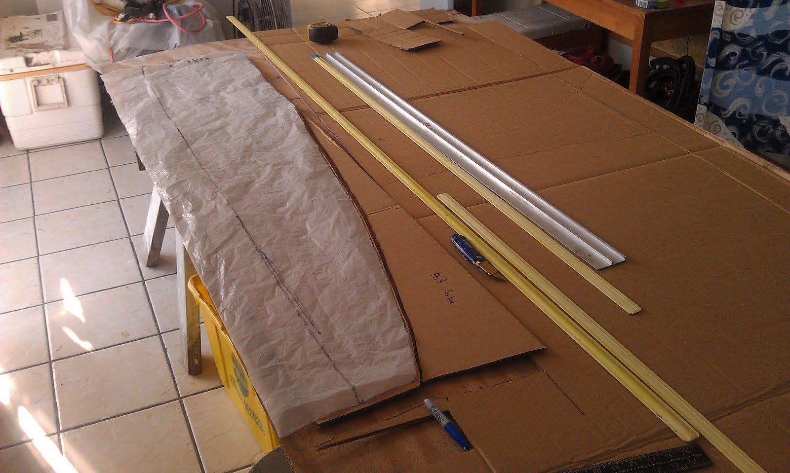
Lonseal Flooring laid out atop a 4'x8' work bench
Initially I planned to create cardboard templates of the cabin sole, but some of the complex joints proved difficult to capture in cardboard. Based on past successes with plastic sheeting as templates when sewing, I switched materials.
using plastic sheeting to trace out cabin sole sections
The plastic proved ideal for capturing the shape of the floor sections, but less effective than cardboard to test fitting all the pieces. No problem... I transferred the plastic patterns to the cardboard.
The cardboard provided stiff templates that I could piece together for test fitting on C'est la Vie's sole.
Once satisfied with the fit, I removed the center panels from the boat and together with the cardboard reconstructed a portion of C'est la Vie's cabin sole atop the Lonseal.
test fitting cardboard templates in C'est la Vie
Laying it out in this manner allowed me to ensure the holly strips would line up well along the length of the galley and salon. The material proved relatively easy to cut with a razor knife and straight edge.
using a razor knife an straight edge to cut the Lonseal Flooring
The curves were cut free hand. Some of the shapes. like the one below that fits around the galley sinks, proved quite whimsical.
I chose to begin the glueing with three of C'est la Vie's removable floor panels. This allowed me to work with the unfamiliar two part Lonseal adhesive #300 in a more ergonomic environment than the hull of the boat.
Albeit sticky and slimy at the same time the glue proved easy with which to work. It must be troweled on, but has a long open working time. The total dry time is 72 hours. Checking the work this morning 14 hours after application, I am pleased with the results.
gluing the new flooring down
(pssst: don't tell Anne I used her rolling pin.)
To Be Continued....


Tuesday, April 23, 2013
Sewing new bug screens for hatches
Aboard s/v C'est la Vie, Jeff and Anne regard sewing as a "purple" job. Today, it's Jeff's turn...
Our existing hatch screens, made by Anne over 7 years ago, grew threadbare. So now it is my turn to sew the hatch screens.
With all the Outward Bound Staff departed we utilize the large spaces in the Sunset Island Lodge as work areas
The west end of the dining room converted to sewing loft.
Having ample space to lay out projects is incredibly helpful. For this endeavor a portion of the dining room became the sewing loft and the salon floor a space to draft out patterns.
I utilized plastic sheeting for the pattern material. Patterns represent the "no-see-um" screen portions of the hatch covers. Due to it's light weight I find the screen difficult to work with so patterns assist with the layout and cutting.
Basic geometry - a framing square,
straight edges, a 3' piece of string,
and a tape measure were used to
create the patterns.
Fortunately C'est la Vie's two hatches are square. The center hatch frame measures 22" x 22". To leave ample room for operating the hatch, I created the pattern based on a 24" square. The forward hatch measured 20" x 20" thus I used 22" for the pattern.
Each hatch screen consists of two panels of "no-see-um" material. The curved section wraps around to form the sides and back of the cover. The rectangular section follows the arc of the leading edge of the hatch as it moves from a close to open position.
Two patterns - the upper two panels
are for the smaller forward hatch.
The larger patterns in the foreground
are for the center hatch.
I use two sided tape to join and test the patterns. Satisfied with the fit, the patterns are laid atop the screen and weighted down to hold the pattern and fabric stationary and wrinkle free while cutting.
Ready to cut the screen. Battens, straight edges,
and a square are used to hold the fabric &
pattern stationary while cutting.
Attempting to cut clean edges on the screen is futile. I hide all the edges of the screen in the finish product.
For joining the screen sections prior to sewing, I use two sided basting tape (I gave up on pins a long time ago.)
Joining the two screen sections with basting tape.
The screen material is too flimsy to securely hold stitches. My solution is to use 1" nylon webbing as binding tape on the screen to screen seams. This method has the added benefit of hiding those rough edges on the screen.
Finally time to begin sewing.
We own a Sailrite LZ-1 and purchased a 1" binding tape attachment along with the machine. This attachment is a must have in my opinion. Similar attachments are available for most machines.
To more easily differentiate between to hatch screens, I used yellow binding tape on the center hatch and blue tape on the forward hatch.
Filling tubular webbing with lead cast net weights.
Tubular webbing filled with lead cast net weights serves as the ballast in base of the hatch screen. The lower edge of the screen and the weighted webbing are hidden inside a Sunbrella base.
The long sunbrella base sections.
Since the sunbrella is a heavy fabric and the base sections are simple in shape, I did not create patterns for these pieces.
Sewing the base proved more complex than I originally speculated. Initially the two sections of the sunbrella base were sewn onto each side of the screen (i.e. interior & exterior.) Next I tacked one end of the weighted tube onto the sunbrella base. Finally I joined the two bottom edges of the base.
Test fitting the final product.
Can't say I'm eager for a buggy night at anchor, but at least we are a bit more prepared.
More images from this project are available in the Hatch Screens - Spring 2013 photo album.


Tuesday, February 12, 2013
New Companionway Screen (a.k.a Reuse/Recycle)
Over at s/v C'est la Vie, Jeff takes on the bugs, in a recycling kind of way. It's a zero-cost solution:
Our existing companionway screen was ill fitting along the sides and bottom of the opening. When a day off presented the opportunity for some project time I collected an unused dive weight, a retired Outward Bound tent, old tubular webbing, and sunbrella scraps left from previous projects and set about creating a new companionway cover. Using our well fitting cloth companion way cover as a template, I began by creating the weights for the top and bottom. Filling tubular webbing with the lead shot from the dive weight was my initial plan.
But once full of lead I felt the tube's stiffness along its length would inhibit it from conforming well to the irregular topography of the top of the cabin.
Using the light weight fabric from the retired tent body, I sewed a larger diameter tube for the upper weight.
Despite receiving more lead the thin nylon and larger cross section served to create a much more supple weight for the top.
Cutting the no-see-um proof mesh screen proved to be much more challenging than anticipated. After a few failed attempts at straight cuts, I resorted to marking out the proper dimensions out on a sheet of plywood; tacking the mesh out on the plywood atop the lines; and then using a razor blade to cut the mesh to size. This system worked well. The relative stiffness of the sunbrella as compared to the screen was easy to lay out and cut to the correct dimensions.
I do realize many people lay out sewing projects with pins, but for me two sided basting tape is my go to product. Using the basting tape I assembled the screen one side at a time with the tape and then sewed it together.
The sewing order went vertical sides, the bottom, and then the top. I added a sunbrella wear patch at the location that the companionway latch contacts the screen.
I gave our old screen covers to a fellow sailor in exchange for some lead shot. Once he delivers the lead I'll begin replacing the screen covers on our two cabin hatches.


Thursday, October 25, 2012
Sometimes it's the little things
Over on s/v C'est la Vie Jeff has been working on a big project: refurbishing his engine room. Now this certainly does not qualify as a "small" boat project. But in the midst of this, he has found one of those small things that can be more important than the big ones.
One of the few items remaining in C'est la Vie's engine compartment is the drive shaft. The drive shaft is a solid stainless steel rod that connects the engine inside the boat to the prop outside the boat.Inspecting and replacing hose clamps is a "small" boat project we should all perform, annually at the least.
C'est la Vie's shaft and shaft seal were replaced in 2007 Traveling from the prop towards the engine, the point where the shaft passes through the hull it is supported by shaft log. The log is a bronze tube with rubber bushings. The log relies on water from outside the hull to serves as a lubricate thus reducing wear and friction. Directly forward of the log is our shaft seal. The shaft seal allows the shaft to spin freely yet prevents water from entering the boat. In 2007, we replaced the shaft, shaft log, and the shaft seal (here is a link to the photo album - Replace Shaft, Log, and Seal - fall 07)
During the 2007 project, we purchased a PYI-PSS shaft seal and had the boat yard complete the installation work. The shaft seal uses a rubber bellows as a spring to press a carbon flange against a spinning stainless steel rotor. The carbon flange and stainless steel rotor are very smooth and when pressed together create a water proof seal. As with any hole in the hull of the boat a failure of this system can cause the boat to sink.
the newly installed shaft seal - Fall 2007
Since all the components of the shaft system were new in 2007, I left them in place and did not intend to replace any parts. My experience over the weekend has me questioning this decision.
C'est la Vie's Shaft Seal - Sept 30, 2012
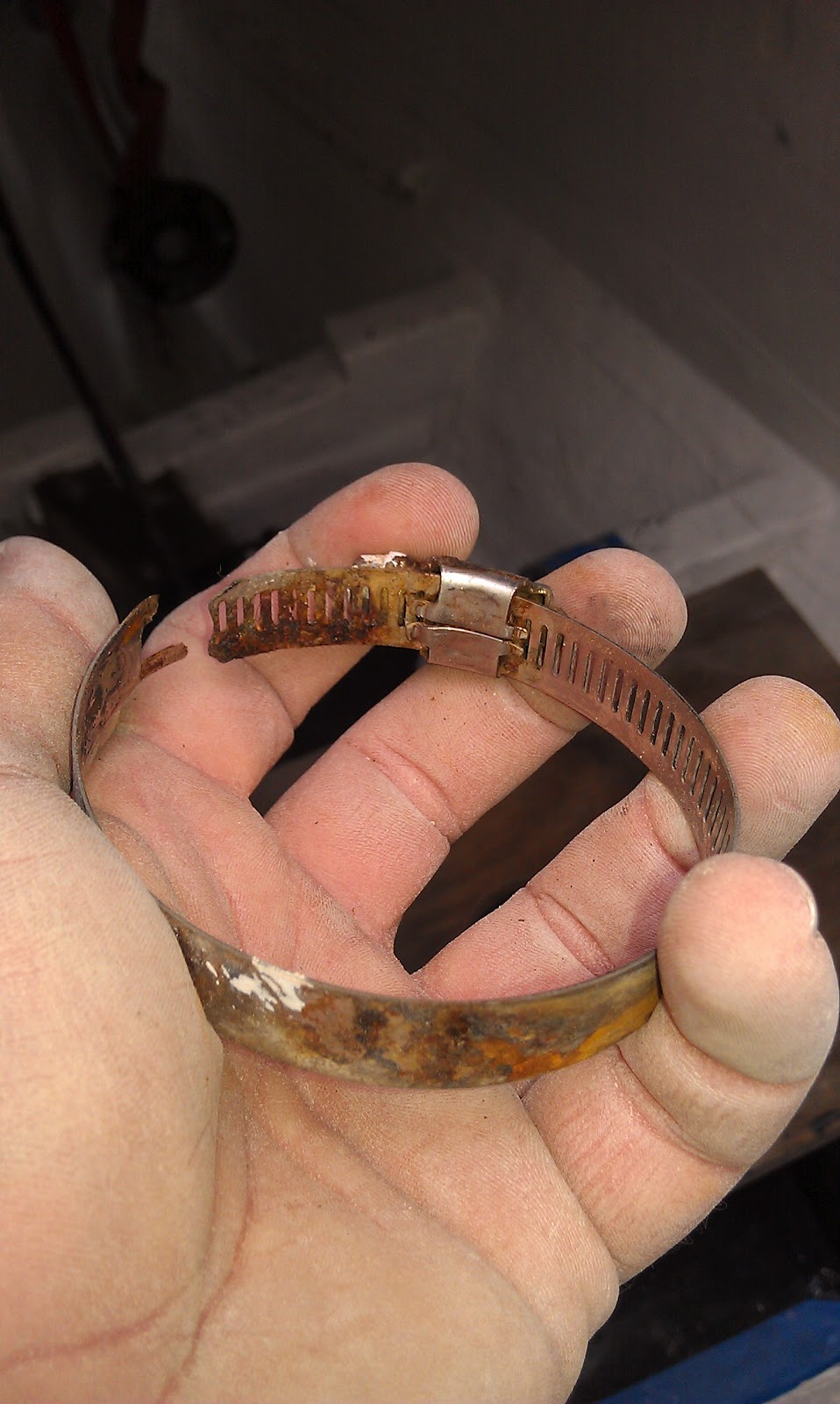
While sanding between coats of primer in the bilge, I noticed a paint drip on the aft most of the shaft seal's four hose clamps. Using a scotch bite scrubbing pad, I reached back to remove the paint drip. Instantly the hose clamp broke in my hands.
the stainless steel hose clamp that broke in my hands after 5 years of
service on our shaft seal.
Alarmed I grabbed a nut tool and attempted to loosen the other hose clamps for an inspection. The very next hose clamp I touched, the forward most clamp, broke as I torqued on the hex head. Yikes! Failure of these clamps can sink the boat. The clamps used on shaft seal were provided by the manufacturer, but are not of the quality I expect for critical through hull fittings. Not all hose clamps are created equal.
Without a doubt all hose clamps on board a boat should be stainless steel, but even among stainless clamps there is a broad spectrum of quality. Clamps used in critical areas (i.e. through hull fittings, engine coolant lines, engine exhaust lines, black water systems, etc.) must be ABYC approved 316 stainless steel with a non-perforated band.
an ABYC approved 316 SS hose clamp with a non-perforated bans will replace
the bands on our shaft seal.
How does one identify the various quality of clamps? The easiest test is to run a magnet across all hose clamps on the boat. If the magnet is attracted to the clamp then the clamp contains ferrous metal that will easily rust. Any clamp attracted to a magnet needs to be kicked off the boat ASAP. I keep a magnet in my tool box expressly for testing hose clamps, bolts, screws, etc. If any of these items do not pass the magnet test then off they go.
Hose clamps that will pass the magnet test are appropriate for non-critical boat systems (i.e. tank vent lines, fresh water plumbing, etc.). If the clamp is destined for a system that is considered critical then it must pass two additional tests. First is the band non-perforated? A non perforated band is stronger, better resists rust, and provides more uniform pressure around a hose. Secondly the hex head on the clamp must be 7mm.
I'm unsure if the 7mm hex head is a brand specific standard or if it is set by the ABYC. All high quality AWAB Hose clamps have a 7mm head so I look to this as an identifying feature of high quality clamps.
If your using the 7mm head as standard of quality then I recommend purchasing a flexible shaft 7mm nut tool to compliment the clamps.
It is worth noting an exception to my hose clamp rant. As hose diameter increases to 2" or greater and/or if the hose has a wire for additional strength (e.g. engine exhaust systems), then t-bolt hose clamps are recommended due to their ability to provide increase pressure on the hose.


Subscribe to:
Posts (Atom)


