As I continue to work on my book on "Faster Cruising" I found myself feeling like the cobbler with no shoes for his children; I don't always follow my own advise, even when I know I'm right. In the book I argue that cruising boats are often lack the rigging and hardware needed to make basic trim adjustments quickly and easily, as though cruisers don't care about efficient sailing or understand the fine points. I care, but I have to admit my cruising cat doesn't have the quick access to fine trim that my performance cat had. I aim to fix that.
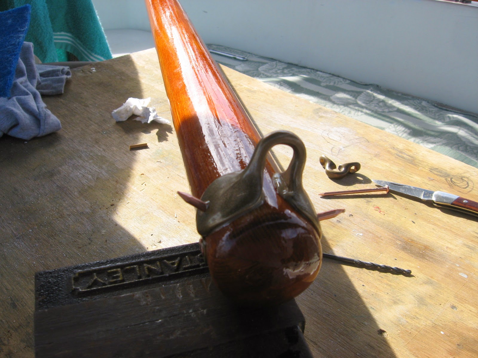
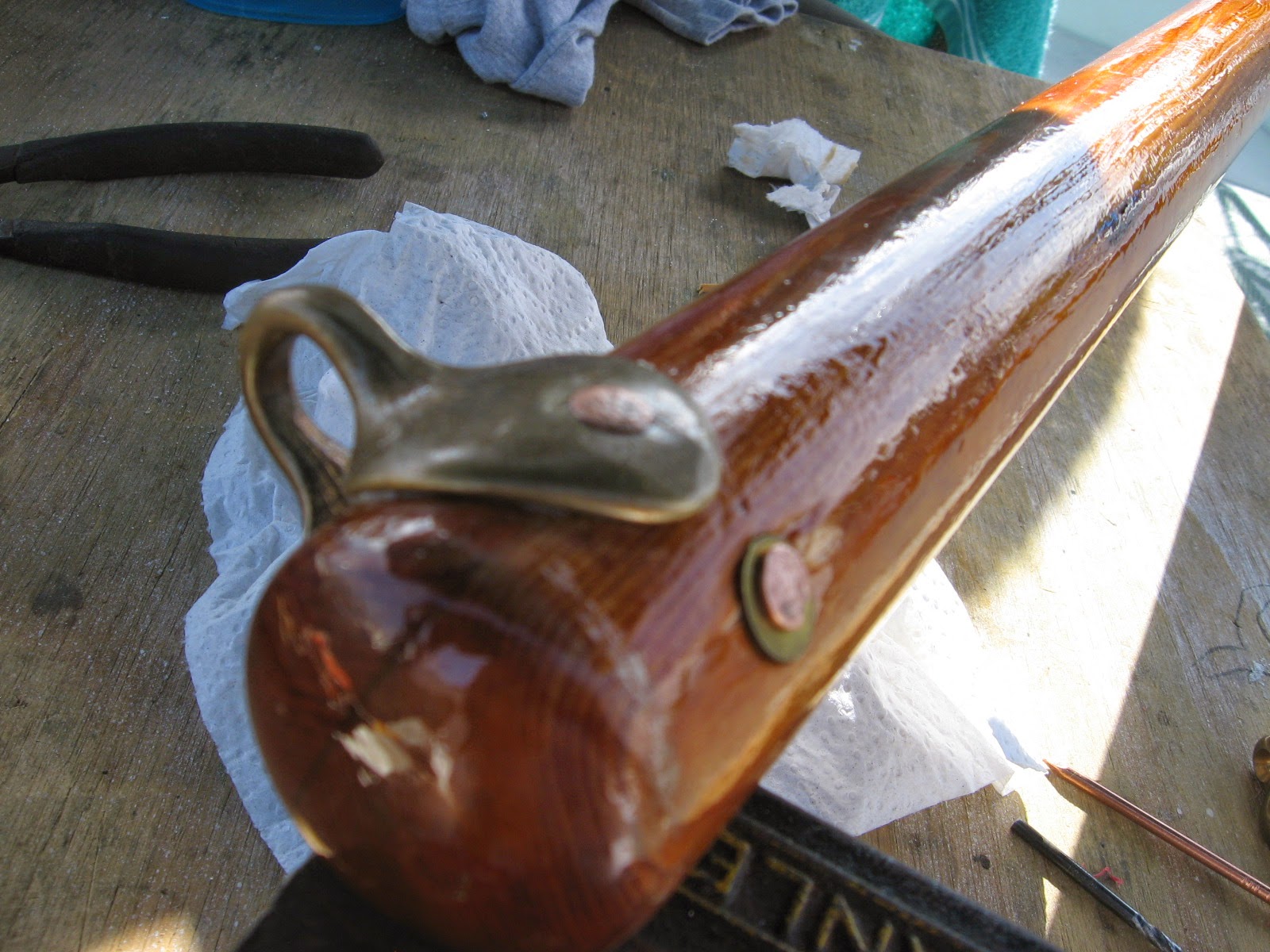
Case in point. My PDQ 32 came with a good boom and internal reefing, but the main outhaul was secured to an undersized cleat . To tension it under load, you take the tail to a mast-mounted winch, wrap the line under the cleat, and lift the line sharply when taking the line off the winch in an attempt to minimize slippage before that first wrap is on the cleat. Boy scout at best.
A few days ago I removed the undersized cleat (closely spaced holes on the seam) and I tapped four new holes to secure a proper jammer. Now I can ease the outhaul in a blink and tighten with a winch in control.
The smaller line is for the lazy jacks.
Why a double jammer? The few times I have found myself sailing with three reefs (winds gusting to over 30 knots) I found I needed a better way to winch the clew down. The tack is easily secured with a loop through the reefing tack and under the gooseneck, but there is no internal rigging for a 3rd reef. Thus, I tie a bowline around the boom under the reef clew (like the other reefs), go up through the reefing clew, and back to a snap shackle-equipped snatch block at the main outhaul. From there the reefing line is threaded through this new jammer, allowing a mast mounted winch to tension the clew outhaul.
The only challenge is to remember to thread the reefing clew while hoisting.
[The jammer came courtesy of freecycle--it patiently awaited re-purposing for several years in one of my might-need bins. Whooppee!]
Showing posts with label rigging. Show all posts
Showing posts with label rigging. Show all posts
Tuesday, November 21, 2017
Outhaul Jammer
I'm working thru my backlog - this is an old post from Drew at Sail Delmarva - so old in fact that he has sold this boat and gotten a new one since this was posted. And the book he mentions has already been published - I recommend it and several others he has published. You can find them in his bookstore.


Tuesday, June 2, 2015
Forestay Built From Scratch
Most sailors regard standing rigging with a kind of religious awe... that only wizards of the fourth class are allowed to make modifications to it. But not Rick aboard s/v Cay of Sea... But it does require attention to detail. Here Rick tackles creation of a new forestay:
Well, not from scratch exactly. I purchased the end terminals and wire and assembled the stay, which is definitely more expensive than having a stay made up by a rigger with swaged terminals. However, as I gradually replace rigging wire, I want to replace each piece with shrouds and stays that I built with Sta-Lok fittings. I want the knowledge and skill required to re-rig without having to hire out work to a rigging shop, and the expensive terminal fittings are reusable.And then there was a follow-up post, where Rick's attention to detail caught a subtle problem. This may be the most important part of this post - taking the time and attention to say, "Hmmm... something doesn't seem quite right." This is where the person in a hurry would have produced a disaster down the line. But not Rick:
I learned some interesting things during a phone call to riggingonly.com. Tom was very helpful and knew all the products, sizes, and orthodoxy like the back of his hand. I had questions for him regarding sizing of eyes and pins, because what I found on my rig didn’t make sense:
Why were they different? Tom suspects that when the boat was built, the rigging contractor didn’t talk to the builder or designer, so there were some missed cues and make-dos. Tom feels like the rig should have been designed with 3/16″ wire – and most of it was – except for the forestay and backstay: these are 1/4″. Apparently 1/4″ wire typically called for larger 7/16″ eyes, but the boat was already built with 3/8″ chainplates. . . so there was a make-do fashioned, and it turned out okay – after all, the rig has stood without mishap for 34 years as designed. Best rigging design, however, matches pinhole with pin size exactly. Why 1/2″ eye at the masthead? Not sure. It didn’t match anything up there (7/16″ toggle and pin). And it turns out that simply using a different toggle to up-size the was the wrong approach too. Not knowing that, I asked about reusing the toggle, but Tom said different wire size required a larger turnbuckle, and a different sized toggle. Not only do the pinholes and pins have to match exactly, so do the toggles for the same reason: point loading or stress risers where the size is mismatched will weaken the ultimate strength of the stay or shroud at the terminal fitting. Instead of the mismatched pins and eyes, I will now have 7/16″ pins and eyes at the mast and stem on new 1/4″ wire.
- 1/2″ eye at the masthead
- 7/16″ stemhead pin hole on bow chainplate with 1/2″ toggle on the old Harken furler (which I did not reinstall)
Assembling the stay was fairly straightforward. I installed the eye fitting on one end of the wire after reading the instructions several times, plus consulting other on-line resources.


I was dissatisfied with the second fitting I installed. For a reason I couldn’t understand, the stud end of the fitting wouldn’t accept as many threads as the eye fitting had. Here are photos to illustrate:


Tuesday, May 19, 2015
Steaming Lamp/Deck Lamp Guard
Over aboard s/v Cay of Sea, Rick avoids paying the marine tax by fabricating his own guard for his steaming lamp:
Okay, I’ll admit that I don’t know exactly what to call this thing, but I know what I want it to do – what I hope it will do, if it is robust enough to do so. First, some background:
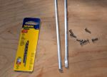
Two years ago my deck lamp was knocked out of the fixture, including the lens (I think), by an errant halyard slap in high winds. Well, that wouldn’t be too bad, except that I had just replaced it. It’s one of those two-pronged halogen 20 watt lamps, and they are sort of pricey. Not only that, but I hate going up the mast. Now I’d have to do it again! There has to be a better system. I imagined at the point, that some sort of cage of rods would be an adequate protection against another halyard slap. I’ve seen them on other boats, but I’ve never seen one advertised for sale, so I have no idea of availability or price. But how hard can it be to make something like that? While the mast is still horizontal and I have time before launch, I thought I would give it a try. I should be able to come up with something.
I went to the hardware store today to look for materials, and came home with 36″ of 1/8″ aluminum rod, eight stainless #6 screws, and a drill bit and tap for #6 screws.
Back in the shop I cut the rod in half and flattened the ends of the two pieces with a 3-pound maul against my closed vice, then drilled holes in the ends for the screws. I used a mill file to clean up the sharp edges.
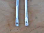
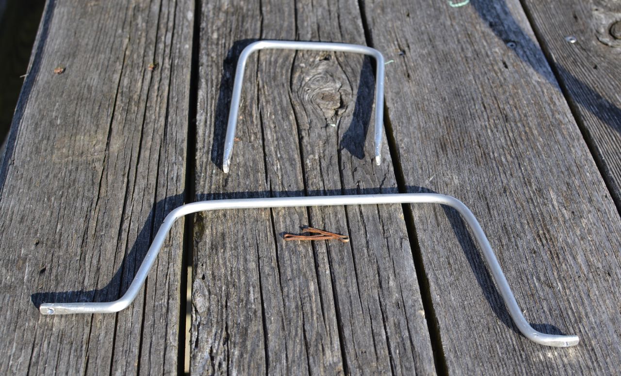
Back at the boat, I estimated the lengths, attachments points, and the approximate locations of the bends. Without a vice on site, I found convenient places to capture one end of the rod while bending the appropriate place against a leverage point. This is what I came up with:
I managed to get one leg of the smaller piece longer than the other. Doesn’t really make a difference. It attached to the mast without complication, but it does bother me that the legs are not exactly the same length. . .
I located the larger piece on the mast first and marked the attachment points. Using a steel punch, I made a small divot point in the mast at each screw hole location to get a clean start with the drill bit. Carefully locating the drill bit, I used significant pressure and slow speed to start the hole (the mast is a curved section, remember? Hard to drill a hole in something like that without having the bit walk all over the place). Each hole started and finished cleanly. I cut threads into each hole with the tap, then ran a screw into it to ensure clean threads. If you never tapped a hole, it’s an interesting process. Everything is extremely low tech, except for the tap itself – which is hardened steel, tapered at the point, with the cutting threads beginning immediately. I use a small adjustable wrench to turn the tap a quarter turn at a time as I guide it into the hole as perfectly perpendicular as possible. It’s helpful to back the tap out a quarter turn after every complete turn or so, to clean the metal debris from the cutting threads.
I marked, drilled, and tapped for the second (port-starboard) piece next, then mounted both pieces with screws well bedded in TefGel. TefGel is a non-conductive corrosion inhibitor, and it allows me to use stainless fasteners into an aluminum mast without threat of galvanic corrosion. Every place I’ve used it on the mast has been completely corrosion-free since I refit the mast eight years ago.
In case you’re wondering, sheet metal screws, or self-tapping screws are an inappropriate fastener for this application. In fact, anything screwed into the mast should be done with machine screws. They have much finer thread than self-tapping screws, and hold much more securely. I like what Don Casey says about sheet metal screws in a mast: “I’ve never seen a sheet metal mast . . . ”
Point taken.
After fitting both pieces, I linked them with a zip tie, reasoning that having them linked together would give them a bit more rigidity (4 attachment points, vs 2).
Here’s the finished product:
Nice rounded features should allow halyards to slide right off and past the light. Cost? About $10, including the drill bit/tap set. We’ll see if it does what I hope it will. Although the rod is quite bend-resistant, the fasteners could be the weak point. As long as they don’t get wobbly, I think it will be fine. They are torqued as tight a I dare and seem quite sturdy, although it may be smart to install lock washers under the fastener heads. Any opinions out there about this?


Tuesday, May 5, 2015
New Spreaders For The Mizzen
[Sorry about the re-post of this one. I just opened it to look at something, and Blogger turned it back into a draft. ??!?]
This post originally appeared on Windborne in Puget Sound
It's funny, isn't it - how something like this can prey on your mind - kind of subconsciously, but still gnawing away just below the surface. Just like the rot - slow but relentless.
Yes, I've known about the rot in our mizzen spreaders for a while now. And I have been intending to deal with it for all that time, but the "right" time hadn't occurred - until now.
So I tied off the mizzen halyard to act as an auxiliary cap shroud and climbed the mast with my tools. Removal of the spreader was far easier than my worries had been leading me to anticipate, even tho it had been up there for 37 years, untouched and uncomplaining.
I had decided that the replacement spar would be made from pressure treated lumber (like the second-generation bowsprit) so that rot would never again be an issue. Now if you have ever hoisted up pressure treated lumber at the lumber yard, you know that it is heavy. And heavy is not good aloft on a sailboat. But most of that weight is water:
Well it only took a couple of hours with a skill saw, power plane, belt sander, and a router to duplicate the shape of the old spreader:

If you've ever cut into a pressure treated board, you know that despite the violence of the treatment process, the treatment does not reach the core of the board. And since the spreader tapers from 1-1/2" thick at the root to 1" at the tip, and from 5" to 1" side to side, a lot of wood was removed from the surface and from one side. Tapering the thickness and cutting away the sides revealed wood that was only lightly treated. What to do?
People who handle pressure treated lumber day in and day out (building decks, for instance) have always had to deal with the cut ends of boards, where the untreated core gets exposed. Long ago they found the answer:
This stuff, which you can find now that you know its name, is just the ticket. You just paint it on and wait for the solvent to evaporate. Wear rubber gloves - its not nice stuff.
And now, even tho I still have one more spreader to go, it feels like an invisible weight has been lifted from me. The subconscious mental anxiety that was silently eating away at my contentment, my satisfaction, my peace, is now gone, just like the rot.
This post originally appeared on Windborne in Puget Sound
 |
| Rot. |
Yes, I've known about the rot in our mizzen spreaders for a while now. And I have been intending to deal with it for all that time, but the "right" time hadn't occurred - until now.
So I tied off the mizzen halyard to act as an auxiliary cap shroud and climbed the mast with my tools. Removal of the spreader was far easier than my worries had been leading me to anticipate, even tho it had been up there for 37 years, untouched and uncomplaining.
 |
| More rot at the root. |
To pressure treat lumber,That's why the wood is so saturated with water when you buy it. But if you simply let it stand in a reasonably dry place for long enough, it will return to a more "normal" moisture content - and much lighter weight. In fact, the replacement spreader is actually lighter than the old one (which of course does have a lot of water in it due to the rot).
- it is put into a sealed vessel,
- the vessel is evacuated, removing nearly all the contained water in the wood as well as air trapped in its porosity.
- Then after a suitable degassing period, the water-based treatment solution is admitted to the vessel, and it is pressurized, forcing the solution deep (well kind of - see below) into the wood.
Well it only took a couple of hours with a skill saw, power plane, belt sander, and a router to duplicate the shape of the old spreader:

If you've ever cut into a pressure treated board, you know that despite the violence of the treatment process, the treatment does not reach the core of the board. And since the spreader tapers from 1-1/2" thick at the root to 1" at the tip, and from 5" to 1" side to side, a lot of wood was removed from the surface and from one side. Tapering the thickness and cutting away the sides revealed wood that was only lightly treated. What to do?
People who handle pressure treated lumber day in and day out (building decks, for instance) have always had to deal with the cut ends of boards, where the untreated core gets exposed. Long ago they found the answer:
 |
| Want to rot-proof some wood? This is just the ticket |
 |
| Add a coat of epoxy to permanently seal the surface. |
 |
| Bed the hardware in polysulphide. |
 |
| A couple coats of paint, and et voilà! |
Thursday, February 19, 2015
Boo Boo's Spars
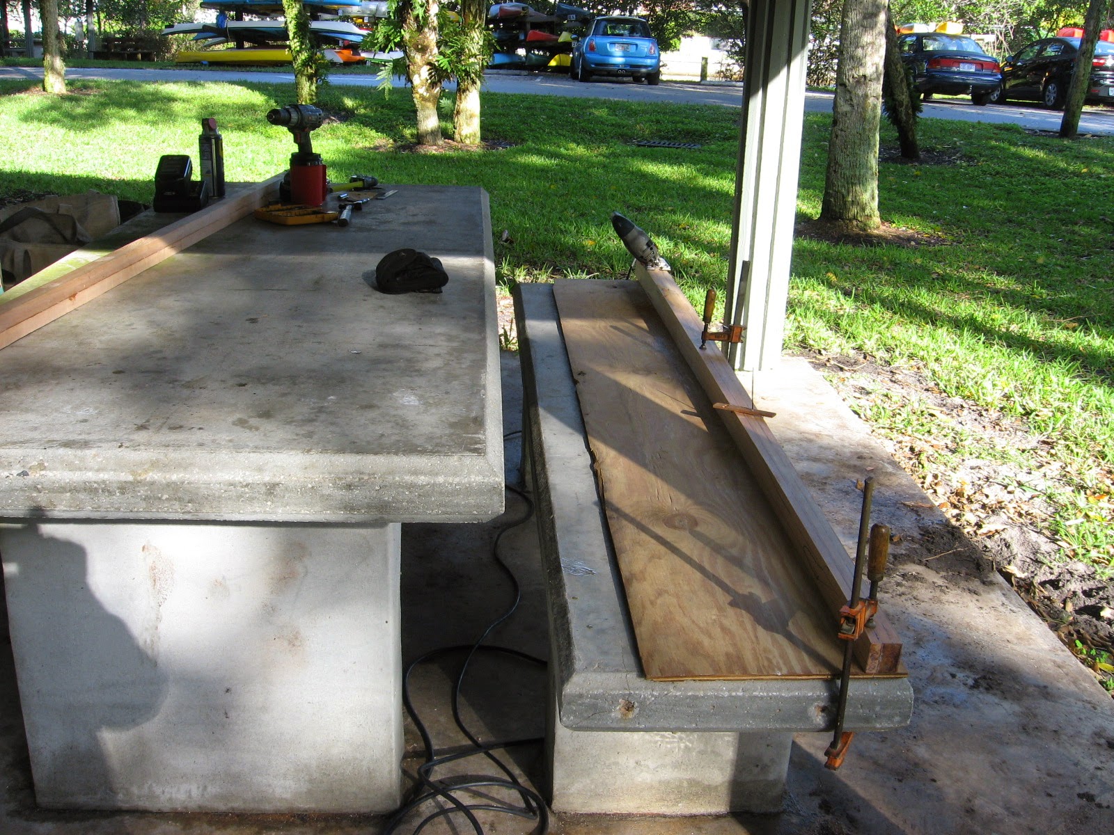
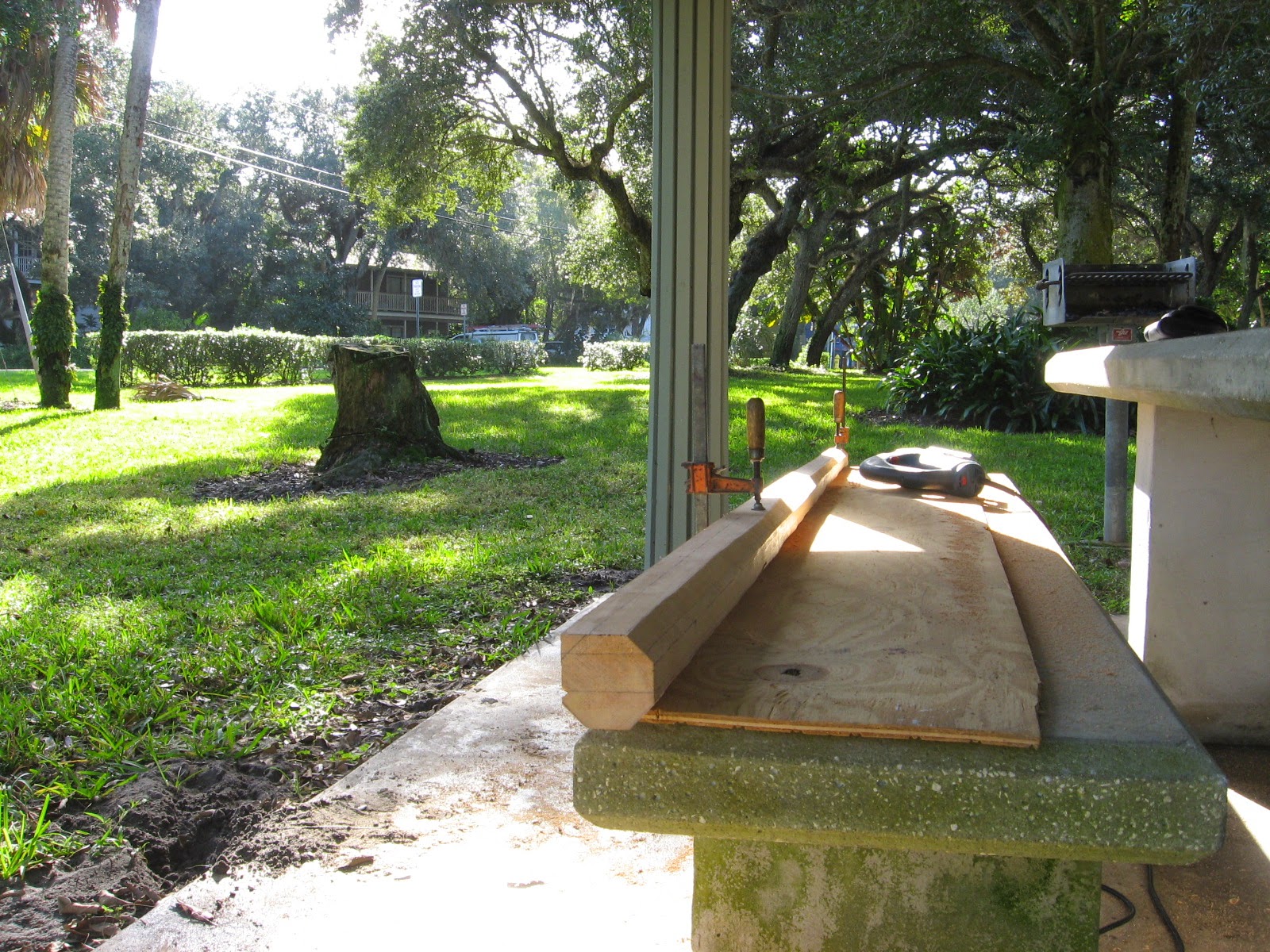
In which Ken of s/v Painkiller constructs spars for a Dyer dinghy on a park picnic table, using only hand tools...
All I want for Christmas is a Dyer sailing dingy, I said out loud half in jest to a friend at the marina, he got on his phone and I heard him say, "you still have that Dyer dingy for sale, how much? He looked at me and said $300 about 4 miles from here. I told Vicky and off we all went. A 1991 Dyer Midget sailing dingy minus the lower mast section, the boom and sail and oar locks. It came with the upper yard (to the mast), the complete rudder, daggerboard and a set of oars. I snatched it.
Once I glued up some straight grained fir that I bought at the local lumber store I brought it to shore to my makeshift shop, the concert picnic table behind the cruisers lounge and laundry. After squaring up the stock for the round mast with hand planes I drew out a taper for the upper two thirds of the mast.
With this very crude but simple jig I was able to draw lines that tapered the "square" to the desired top dimension, 1 3/4". The base is 2 1/2"
Next is to cut the corners off, making 8 sides to the spar staying away from the lines. It was very tough using a jig saw for this operation, but a man's got to use as best he can what a man "has" to use.
Certainly not the greatest bench, but enough. The scenery was excellent and the distractions from cruisers were many, but I got by.
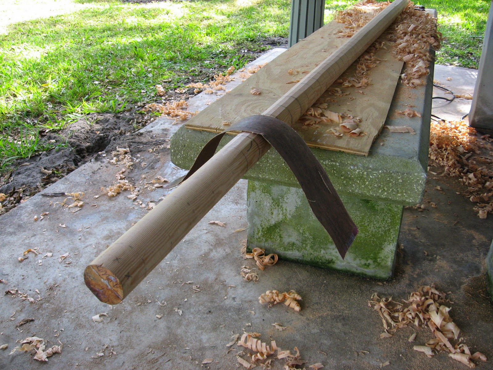
I then carefully planed all eight sides to an even width right to the lines. This gave me the taper I wanted and much closer to the "round" I wanted. I'm sure I could have come up with a way to draw lines on all eight sides again for a perfect 16 sided spar but I chose to knock down the 8 high spots by eyeball with the hand plane.
It was definitely close enough with 16 sides to dig right in with the truly grunt hand work, sanding against the grain with a cut opened belt sander pad. I think it was 50 grit.
Then of course some proper sanding down with the grain to bring to finish.
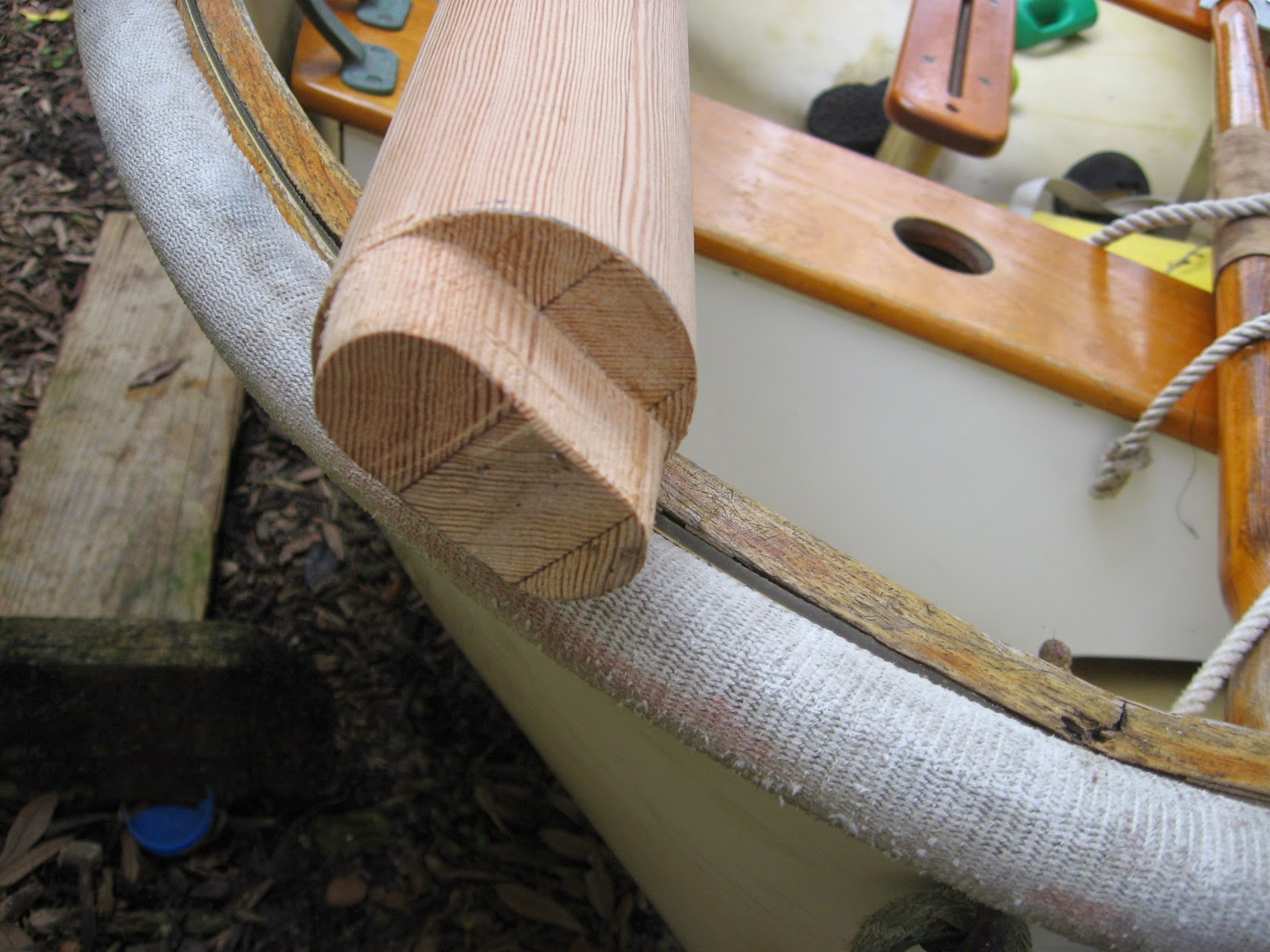
With the fitting and shaping of the mast step I was ready to move onto the rectangular boom.
My crude but effective set up to use a round-over bit for the boom and an evening beverage for a good day work.
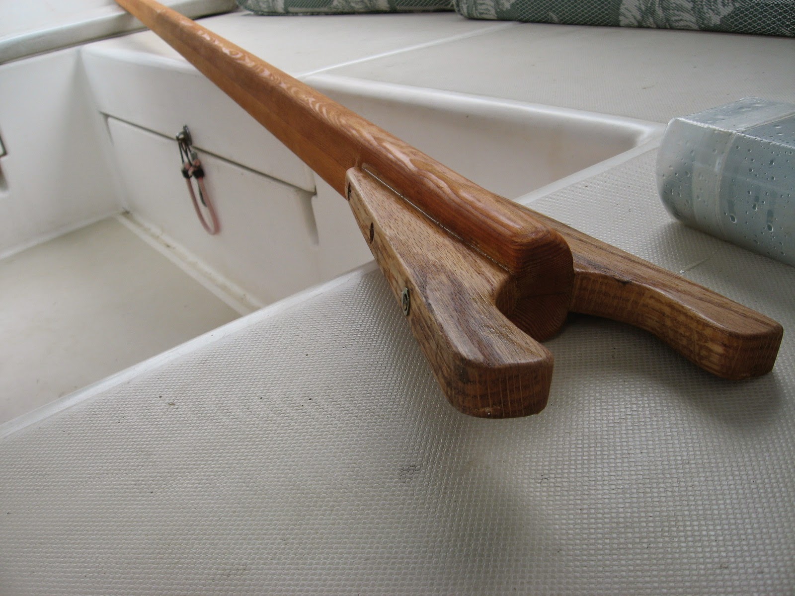
The oak jaws on the boom were pretty straight forward other than I had riveted the end prior to getting the bronze fitting, which is held in place with nothing "but" the rivet, so I had to re-rivet twice.
Prettying it up with the leather work and we are just about done. I also made a couple of teak cleats for the mast and boom, threw on a few coats of varnish ...
... spliced some rope work to complete the running rigging. I had bought a new sail from Dyer along with the proper bronze fittings I was missing, but they sent me the wrong part which caused a very long delay leaving me frustrated not being able to set the sail.
The parts finally came in and I hurried to rivet on the yard hook strap eye with the two inch copper nails.
Christmas came very late for me this past year but worth every minute I had to build the missing parts.


Wednesday, December 3, 2014
Snag Reduction--Or Tacking Without Tears
Tacking a boat is a time when all kinds of mischief can occur. With all the sails and sheets loose and being blown/flogged around, it is amazing sometimes what Murphy can pull off. Over at Sail Delmarva, Drew implements one of his typically elegant solutions to keep him in check:
Snagging the lazy genoa sheet on the mast-mounted winches has been my curse since the first day. The clew is just above the winch, and when it slides across the mast during a tack it just loves to loop over the winch, necessitating a trip forward. If I'm lucky, the boat doesn't fall into irons.
I tried a few simple bungees and covers for the winches. No luck. I tried better technique; OK when the wind was light, but otherwise undependable. I tried a line from the spreaders forward to the tramp; too hard to get the tack around. Finally I spent some time looking at it and found a simple solution that works the charm.
The Deflector. I ran a 40' length of 1/4 spectra double braid that I had left over from the end of the self-tacker traveler, through the lazy jack pad eye at the spreaders, and down to the other end of the traveler. It is tensioned with a truckers hitch, but not too tight, as the forces could get out of control. This keeps the sheets away from the winches AND away from the salon hatches , allowing them to remain open even when tacking. I thought it might be in the way, but in fact it makes a nice hand hold in an otherwise precarious area.
The sheet is held far away from the mast and hatch.
However, there is a significant tendancy for the clew eye and soft shackles to jam against the new deflector stays. I tried a few things before coming to a simple and entirely satisfactory solution; the sheets are now attached to the tack via a trianagular sliding bridle.
The Bridle. an 18-inch spectra climbing sling did the trick. It is luggage tagged to the eye and then each sheet is attached with a separate soft shackle. If there is any tension at all on the lazy sheet, the sling opens up into a triangle and sail clew is NOT forcibly dragged across the stay, only the sling. The clew eye is always free to move forward, away from the stay. Additionally, the shackles do not pass all at once, but rather in succession, reducing the drag.
A bit tricky to see, but both sheets are attached NOT to the clew, but to the sling, along which they are free to slide when tacking. Both are attached with soft shackles; this is required because the windward sheets are inside the shroud and the reaching sheets are outside the shroud.
Not a single snag over many tacks in many wind conditions, from ghosting to 25 knots. Why does it take so long to learn simple things?


Tuesday, November 25, 2014
Preparations for Ascending the Mast
Climbing a mast is arguably the most dangerous thing you can do on a boat. Before you take on this task, you should go over the task(s) to be accomplished at altitude and make detailed preparations. Rick on s/v Cay of Sea shows us how:
I installed new deck hardware back in May of this year in preparation for a rigging project. The original idea was to ascend the rig, drop the headstay to the deck, build a new stay then climb the mast again and install it. But there were things to do before I would go up the mast, and one of them was replace the worn out deck hardware through which the line passes.
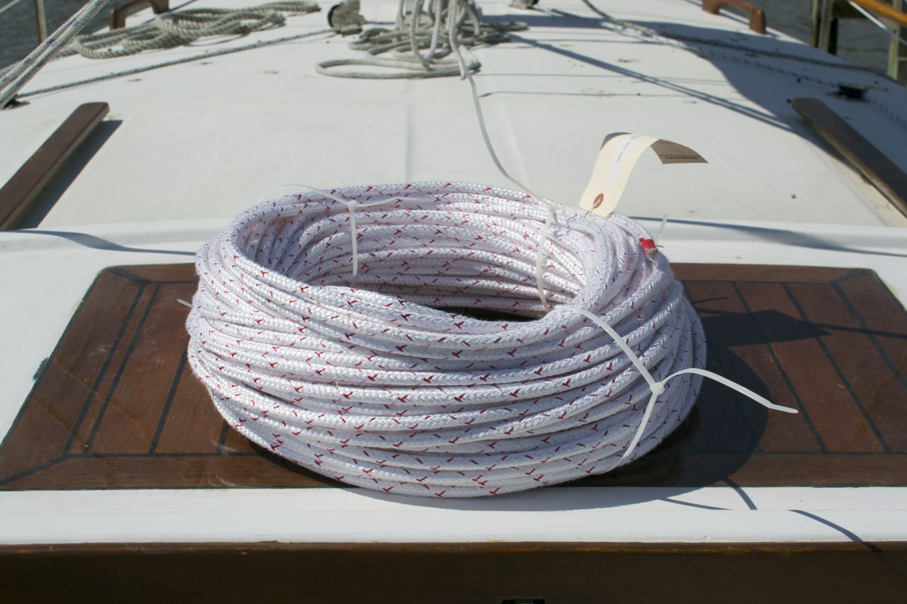
The second item in preparation was to replace the halyards. I researched the ageing characteristics of the StaSet X line that I use for halyards, and it was obvious that the line was plenty strong, even after 7 years’ service, to support my weight. But I wanted a comfort factor that the old line wasn’t going to provide. New line for halyards was called for. The final crippling of my standing rigging as a result of having the steel wire come out of the spreaders kicked me out of procrastination mode, and I ordered the line. About the same time, I noticed an area of chafe where the main halyard passes over the masthead sheave. So it was time to replace halyards, and now I have no guilt over being wimpy about going up the rig with new line.
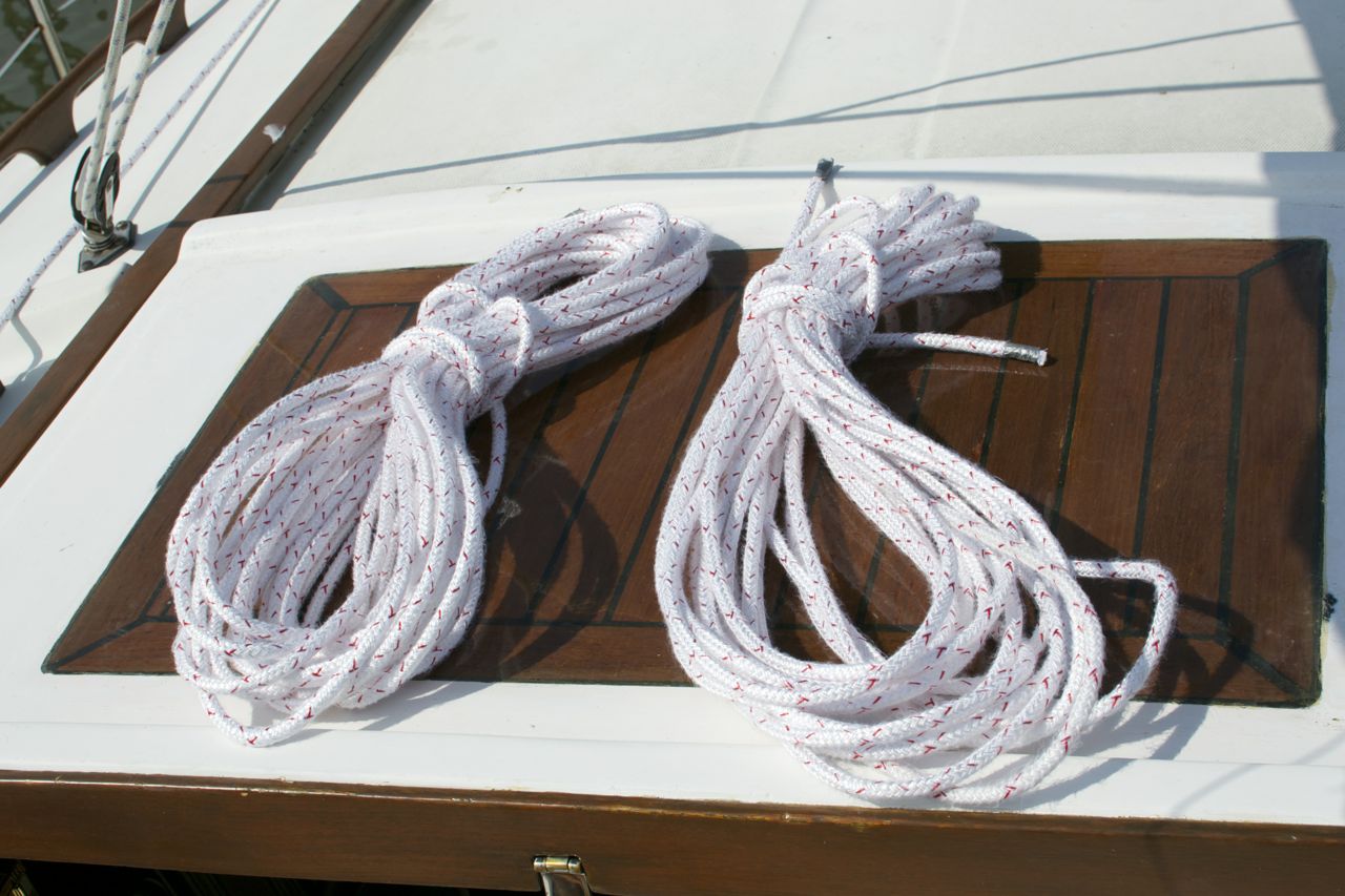
300 feet of 5/16 Sta Set X.
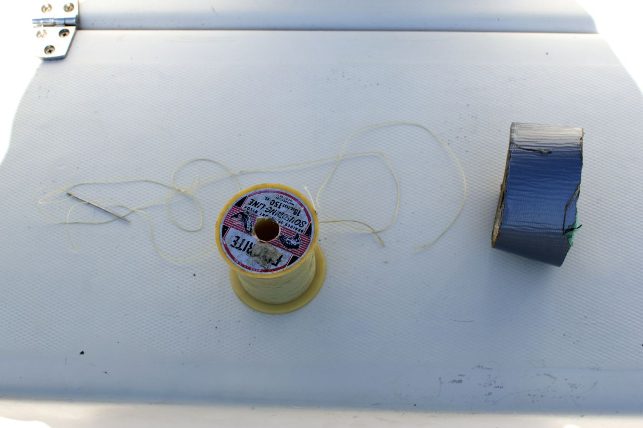
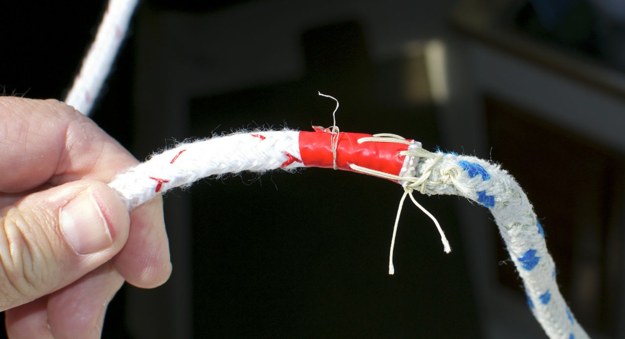
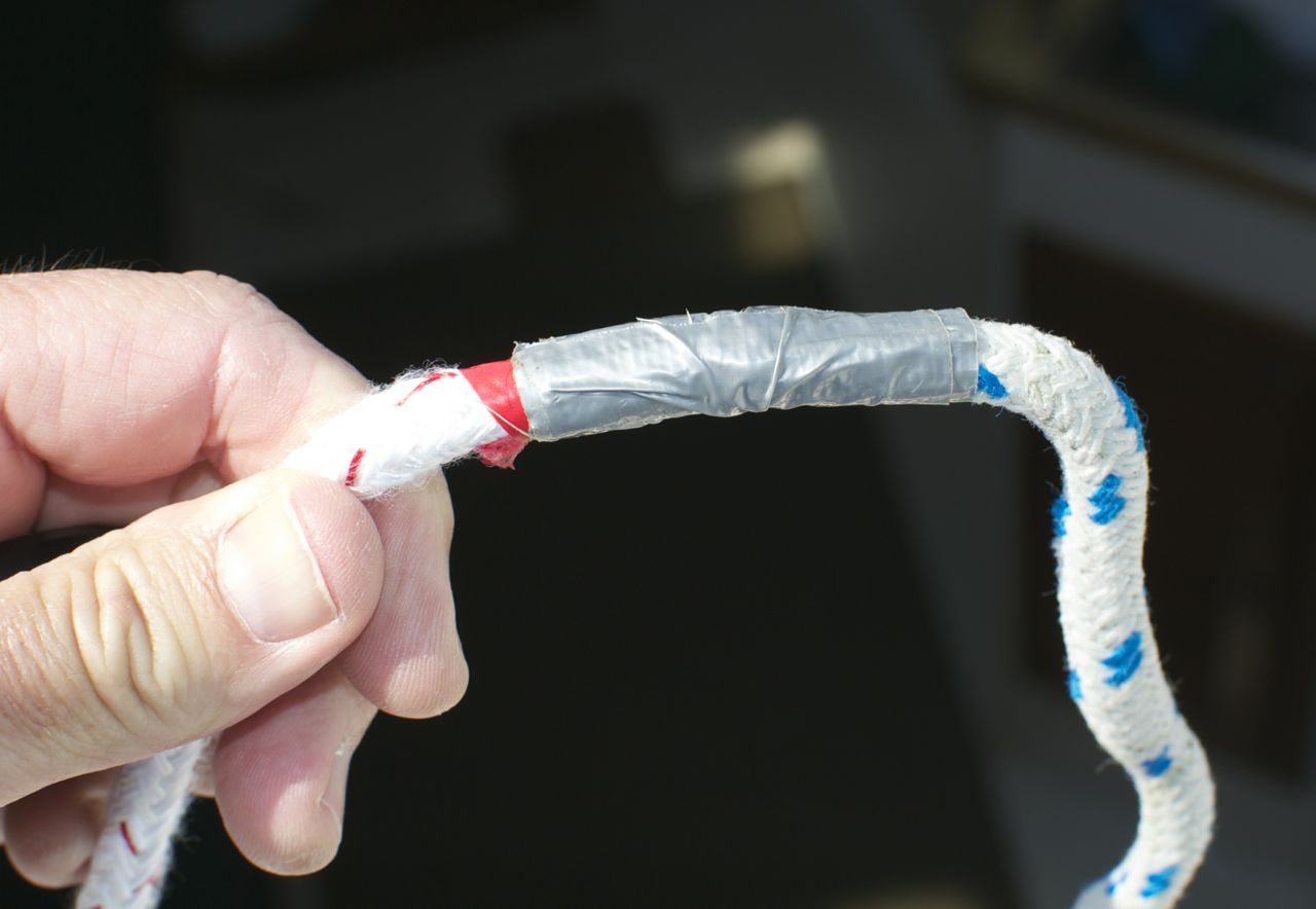
I ran the new line up the mast today. I sewed the new line and old line together at the ends, then covered the seam with duct tape, so it wouldn’t catch in the sheaves at the masthead. When connected and smooth, I simply pulled on the old line until I had new line in my hands.
Tools for installing new halyards: sail repair needle, heavy nylon “squidding line,” and duct tape. A pocket knife is useful too.
Line ends sewn together. This makes a strong attachment that won’t let go. I wouldn’t trust tape alone.
Seam covered with duct tape.
Tomorrow is the day, at least for Part I. I spent an hour today figuring out exactly what I’m going to do up there, organizing supplies, tools, and procedures.
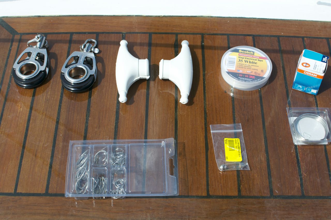
Supplies
Seizing wire, spreader boots, rigging tape, ring and split pins, deck and steaming bulb, 2 halyards, 2 new blocks.
New 70′ halyards. Had to measure 4 times before I started getting the same length of line consistently. Then cut entire length (140′) in half.
Tools
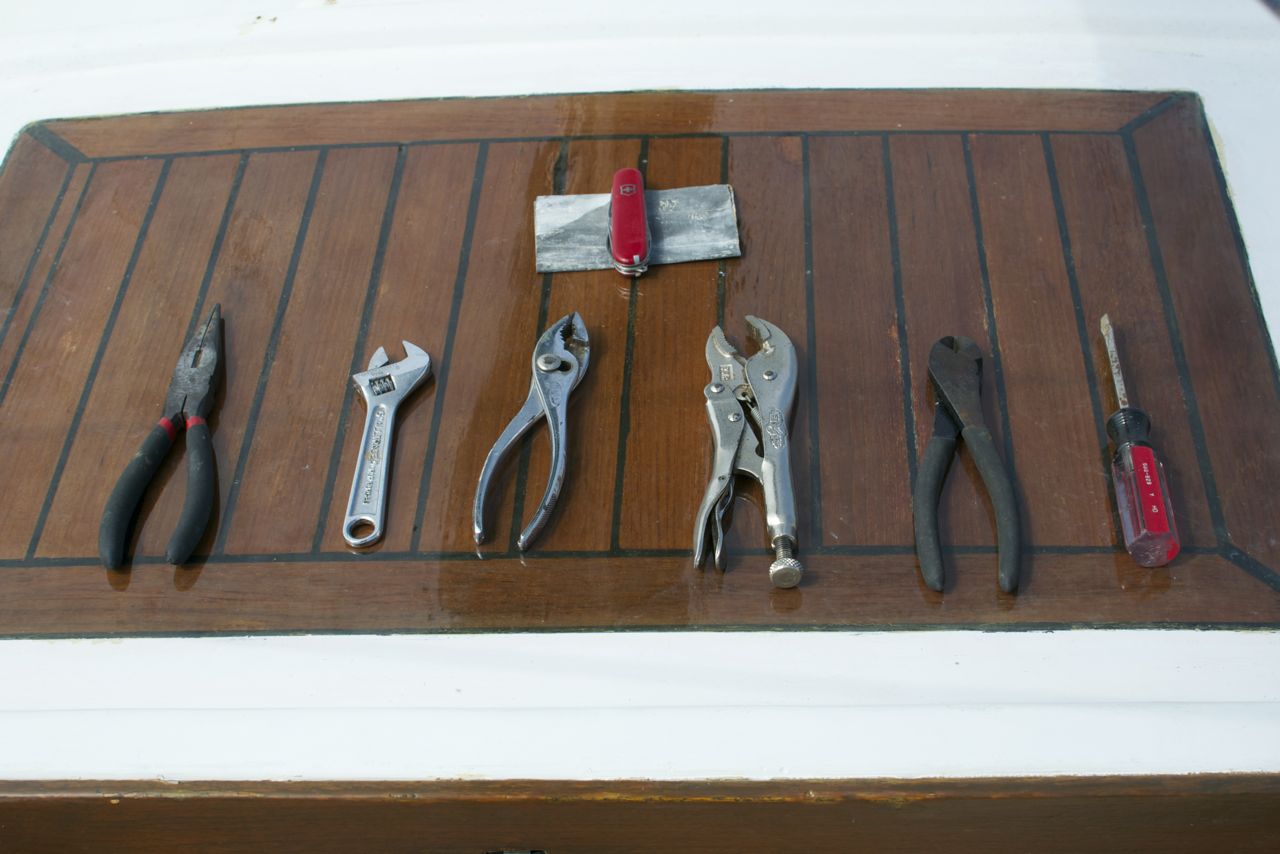
Essential tools. Piece of material under the pocket knife is emery cloth for polishing 12vdc light contacts.
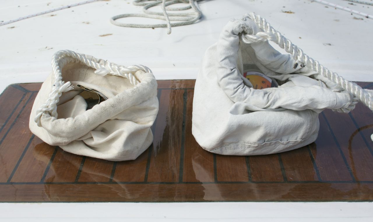
Canvas buckets to the rescue: Tool bag on left, supplies on right.
Order of Work
2. At Steaming/Deck Light
- At spreaders:re-slot cap shrouds and wire/seize in place
- install spreader boots
3. At masthead
- Replace bulbs and test while aloft
4. Descend to spreaders and inspect all fittings.
- Attach new blocks, tape shackles/circular retaining pins
- Rove new line through blocks.
- Use one new line as temporary headstay
- Attach other new halyard to harness as safety line (another deck helper tends this line)
- un-attach old spin halyard
- un-attach furler/headstay and lower to deck
- Check fit of old (original) stay to hardware for match
- pin size conflict at stemhead leaves doubt that masthead hardware matches
- Visually inspect all fittings
Already done
Un-attached furler from stemhead, and secured to rail. Attached old spin halyard to bow pulpit for temporary headstay.
Old furler secured to pulput, removed from stem.
Final Photo – is this where we got the term “poop deck?” Birds have been doing me wrong!
Subscribe to:
Posts (Atom)


