Some amazing photos will be present in this post but maybe not for all public; once the Vahine has left the surrounding of the boat, well in my dream… With that said I was left to ponder on what could be done during this sunny day. so let’s “dive” in one of the most interesting subject of all: oil and seals on a SD20 Yanmar saildrive. Please stop all the applause, I know you are excited but one day somebody will do a Google search and will find the solution to a problem a few years ago we couldn’t!
For the rest it’s just a reverse job and 5 liters of gear oil to complete the job.
Showing posts with label howto. Show all posts
Showing posts with label howto. Show all posts
Tuesday, July 19, 2016
Changing the seal on a SD20 Yanmar saildrive
It has been said (often) that cruising is working on your boat in exotic locations. And while that is an overly pessimistic assessment, certainly cruising cannot be entirely a vacation from maintenance. While Valerie is away, Laurent on s/v Letitgo gets busy on one of those necessary tasks...


Tuesday, April 12, 2016
Autopilot Pump Rebuild
Today Sean and Louise, who live aboard m/v Odyssey, give us a lesson on just how effectively ingenuity and hand-held tools can substitute for the services of a machine shop.This is a post we all should read.
As I promised earlier, I'm writing up the autopilot repair in this separate post, now that we're safely anchored off Fort Macon, near Beaufort, North Carolina (map). I won't cover anything else here, so if you're not interested in the repair you can skip the remainder of the post.
By contrast, if you landed on this post from somewhere else, a little background is in order. Vector has a hydraulic steering system, with most of the components coming from the Canadian firm Jastram. That steering system includes a pair of big hydraulic rams that move the tiller arms and thus the rudder, two manual helm pumps operated by big 30"-diameter "destroyer-style" helm wheels, and an electric helm pump connected to an electronic autopilot. There are also two rudder feedback senders, one made by Jastram that drives an analog gauge on the helm console, and a second that is part of the autopilot system.
The autopilot is a Simrad unit common on boats of Vector's era, developed by Robertson, whom Simrad purchased before themselves being absorbed into Navico. Other than some water intrusion into the flybridge control head, the Simrad system has worked reasonably well since we got the boat, and we're quite happy with it. The main control unit, which nowadays would be called a computer but when this system was released was called a "junction box," a J300X model, has several output terminals to drive a variety of electric helm pumps, although Simrad also sold their own version. We have two control heads for the system, an AP20 in the pilothouse and the smaller AP22 on the flybridge.
There's really nothing at all wrong with the Simrad part of the system. It's an older unit and sometimes it misses or misconstrues NMEA inputs from the chartplotter computer, which tells it where to go in navigation mode, and when such an event starts to send us off in an odd direction we'll often say "go home, Otto, you're drunk." Typically, disengaging and re-engaging navigation mode is all that is required to get past these rare glitches.
The Jastram pump has also run more or less flawlessly until a week ago, when it quit briefly on our way into the Alligator river, and then again permanently while crossing the Pamlico the following day. Given its complexity, there are quite a number of ways in which it can fail, and several of those are electrical or electronic in nature. My first impulse was to start taking apart its integral electrical control box and put a meter on the various signals from the autopilot control unit to see if the commands were even coming through, or if either the thermal circuit breaker or the motor solenoid was not passing power through to the motor.
Motor end cap, full of carbon dust. You can see bits of the commutator in the dust.
That diagnosis revealed in short order that power was going to the motor but the motor was not turning, and removing the motor end cap, which can be done with the motor still attached, quickly revealed why: the commutator had disintegrated. The end cap was nearly packed full of dust from the carbon brushes, and I found bits of the commutator in the dust. Reluctantly, we diverted our course and put into port, hand steering for some eight hours or so.
The commutator end of the armature, still in the motor housing. You can see in-place commutator pads on the left, and missing spots on the right. And more dust.
After deciding to make port in New Bern, NC, I called three different electric motor repair places there. Upon explaining the problem, each told me the motor was not really repairable and would need to be replaced. Each also told me that without the specifications, they could not match anything up to provide a replacement motor. Thus started a lengthy Internet search for either a replacement motor, or an entire autopilot pump.
Some of the broken bits of commutator. No way to reattach these.
In the process of trying to source a motor and/or a whole pump, I learned a great deal about autopilot pumps in general and ours in particular. Now that I know it, it all makes perfect sense, but it's not something I had to think about before.
Our pump is a constant-running pump with a "shuttle valve" or "pilot valve" attached. When the autopilot is engaged, the pump runs continuously and in one direction only. Absent any commands, the fluid leaves the pump and immediately returns via a U-turn in the center of the pilot valve. When the autopilot commands right or left rudder, the shuttle moves in a corresponding direction to send the fluid into the helm lines leading to the ram cylinders in one direction or the other; from the point of view of the valve, this is either a "straight through" or "crossed over" arrangement of the output.
The cover plate from the shuttle valve, showing the fluid flow diagram.
When I started looking into replacement autopilot pumps, the vast majority on the market were not constant-running pumps with shuttle valves, but, rather, reversible pumps. The pump is plumbed directly to the steering lines, and the motor is operated in one direction or the other, by changing polarity, to move the rudder, which stops when there is no power sent to the pump at all. Unsurprisingly, these types of pumps, being much simpler in design, were considerably less expensive than the constant-running types.
Upon further investigation I learned that autopilot pumps, while often sold in catalogs based on boat length, are really sized instead by the volume of the steering ram(s). When you think about it, this makes perfect sense: the pump needs to be able to take the rudder from full left to full right in a set amount of time; 20 seconds is a typical number for automatic operation; half that or less might be required if "manual" steering will be done by means of a follow-up lever. How long it takes the pump to move the rudder is a function of the flow rate of the pump and the volume of the steering ram(s).
Vector has two steering rams with a capacity of 300cc apiece. That means that 600cc must flow through the system to move the rudder from full lock right to full lock left or vice versa. The Jastram pump installed with the system is a 3 liter/minute pump, or a lock-to-lock time of about 20 seconds. By contrast, the largest reversible pump I found, at around $900, was rated for 2 liters/minute, and pumps in the $500 range were more like 1 liter/minute. None of those was going to cut it with our system, and 3 liter/minute pumps, all of which are the constant running type with shuttle valve, are in the $3,000 range. Learning this gave me great incentive to repair the pump we already had.
Somewhere in the process of this research, I learned that a now-discontinued reversible pump, made by Accu-Steer, is the underpinning of our pump. Jastram partnered with Accu-Steer and mated a valve block and a Vickers shuttle valve to their HRP-75 pump to create the Jastram HPU-180 pump, then hard-wired the motor to run in a single, continuous direction. I was able to find a replacement HRP-75 on eBay (which I later purchased as a spare; we should have it in a couple of weeks) and deduce some things about the motor from a partial nameplate in the listing photo.
Between that, the physical characteristics of the existing motor and pump, and the limited specs in my owner manual, I guessed that a 1/7-HP rated motor turning around 1,700 rpm at 12 volts would be sufficient for the task. Motors of about this specification, but with square rather than round end-plates, are available on short notice from Grainger for about $270 or McMaster-Carr for about $190. In either case, I'd have to modify the mounts, but, more importantly, find a way to couple their 1/2" output shafts to the pump's 3/8" input coupling.
After hunting around for quite some time, I came across this motor available on Amazon for just $50 with free two-day Prime shipping. It's rated at 3,800rpm at 24v, or half that at 12v, with the required 150-watt continuous rating. It's significantly smaller physically than the motor it's replacing, which gave me pause, and I knew I'd have to find some way to mount it with its smaller end-cap, as well as adapt its 5/16" output shaft to the 3/8" pump input.
Old motor at left with new one at right. Note the machined lip on the old motor and the four mounting holes on the end cap; in this photo the new motor has already been drilled and tapped for the same mount and "machined" down to the same OD.
With a replacement pump/motor assembly on tap via eBay and nothing to lose, I ordered the motor on Amazon with a delivery for Tuesday afternoon. As soon as it arrived, I set to work. After a quick test to ensure the motor spun properly in both directions, I started on the output shaft adapter. This started out as a length of 3/8" OD, ~5/16 ID copper tubing, less than a dollar for 3" worth at the hardware store in town.
It's impossible to cut a clean end on soft copper tubing, so I had to run my 5/6" drill bit through the tube a few times to get the motor shaft to fit. This after over an hour of fiddling to remove the belt pulley that came with the motor, which, despite being putatively retained by a simple clip ring, was effectively press-welded to the shaft. (I ended up hacksawing it in pieces and then running the motor against a bastard file until the stupid thing fell off.)
Lovejoy-type coupler with the home-made copper reducer fitting inserted.
Once I had the tubing pressed over the shaft on a close fit, I spun the motor up, tubing and all, to cut the tubing to length against a sharp file, then spun it some more against first a file and then an emery cloth until the tubing fit snugly inside the 3/8" Lovejoy-style coupling (actually a Martin brand coupling) that came off the old motor. I then drilled a small hole in the tubing for the set-screw on the coupling to pass through and engage the flat on the new shaft.
With the tubing and Martin coupler in place, I held the motor up against the mating coupler on the pump by hand, while Louise operated the autopilot's non-follow-up mode to move the rudder from full left to full right and back again. I expected to have to grip the motor tightly, but was pleasantly surprised by how little torque was required to keep it in place. The little motor had no trouble moving the rudder, at least at the dock with no water flow past it.
New motor with jaw coupling installed, ready for installation.
That accomplished, the next step was to mate the motor to the pump in some sort of permanent way. The previous motor was affixed with four 10-32 machine screws near the outboard edge of the end cap. The new motor was drilled and tapped for three 10-32 screws a good deal closer to center. Ideally I would be able to use these mounting holes, but the connection to the pump involved a flanged tube wherein the tube portion was very nearly on top of those threaded holes. There was no way to drill the flange for the new bolt holes or get bolts in to them.
Instead I opted to disassemble the brand new motor so that I had the end cap as a loose part, then drill and tap the end cap for the four 10-32 bolts in their original locations. The casting of the inside portion of the end cap made that nearly impossible, and I managed to get two good holes and two somewhat oblong ones, but with usable 10-32 threads nonetheless.
My hokey mounting holes, near the outboard edge of the end cap. The OEM mounting holes, closer to the spindle, are tapped into thicker ribs cast into the end cap for the purpose. I made sure that one new mounting hole, at lower right, also ended up in a thicker part of the casting.
The old motor had a machined lip on the end cap that mated with a lip on the mounting flange. The new motor's entire end cap was just a hair over the diameter of this machined lip, so I put a bolt through the spindle hole, chucked the end cap in my drill, and spun it against a file until the OD just fit inside the lip on the mounting flange. Crude, but it worked.
Once it was all in place and bolted together, we fired up the autopilot and ran the rudder in both directions several times. Other than being a bit quieter than the old motor, we could detect no real difference in performance, but, again, that's at the dock with no water flow. We knew we'd need a sea trial.
Today's cruise down the Neuse River and Adams Creek provided the first real test. It all seems to be working fine, and we made it do several hard-over turns at our normal cruising speed to be sure the new motor would not bog down. Again, other than being quieter, which I attribute to the commutator problems on the old unit, we can't tell the difference. Only time will tell if this inexpensive motor will live up to the challenge.
The new motor does not have externally accessible brushes, so if those need replacing I will need to open it up and do some soldering. But then again, the externally replaceable brushes on the old motor did no good at all -- the brushes still had plenty of meat left when the commutator self-destructed. If this motor burns up in a couple of years, I'll just buy another one for another $50. As it stands now, I have a total of about $55 invested in the repair.
I did buy a 1/2" hub Martin coupling for a few bucks, in case I need to upgrade to the aforementioned motors from either McMaster or Grainger. Those motors can be had in a day or two, so having the coupling on hand will make the swap that much quicker. And I also blew ten bucks on a package of spindle bushings to mate 1/4" shafts to 3/8" couplers, in case I need to change to a motor with a 1/4" spindle. Between the two of them, I should be able to get a workable replacement motor up and running in just a couple of days anywhere we might be, should the current hack quit working.
As I mentioned earlier, I also ordered a used take-out Accu-Steer HRP-75 pump assembly. This should have a good working motor on it as well as the swash-plate pump itself, giving me spares for most of the moving parts of the Jastram pump. The other moving part is the pilot valve, readily available from Eaton/Vickers in stock. I spent just $150 on this used pump, inclusive of shipping, and for that price I'm happy to have the spares even if I never need them.
Tomorrow we will head out into the ocean on an overnight passage, which will be the real litmus test of my repair. I have no reason to believe it will not work perfectly, but the diminutive size of the replacement motor will have me watching it closely for the next few passages.


Tuesday, January 12, 2016
Fender Washers--Basically Useless?
Drew has been at it again... Here he is testing fender washers as might be used instead of proper backing plates for items thru-bolted on deck. Drew made two posts; I have included both of them here.
In the process or researching an article on backing plates, it seemed worthwhile to actually test some washers. After all, it was the failure of fender washers that led to cracking of my deck and the need to remount the winches.
I used a 3/4" pine board as a surrogate for a cored deck and tightened a collection of 1/4" washers untill the first damage to the wood, and until failure. To no surprise, common washers, fender washers, and HDPE were glaring failures, and FRP and thicker metal washers were fine.
(click to enlarge table)
And then there is always the matter of what happens in wet places. Though I like aluminum for ease of fabrication, I also know its limitations.
As ramp-up for some Practical Sailor testing, I thought I would share a preview.
First, unable to secure scraps of deck material for which I could be sure of the pedigree, I laid up some of my own. The testing will based upon 1/2-inch balsa core with (1) 6-ounce cloth and (1) 17-ounce biaxial layers on the deck side and (1) 17-ounce biaxial layers on the under side.
I drill a 1/4-inch hole (no epoxy plug, block of wood on the back side) and tightened down a fender washer against it. At 10 in-pounds (about 675# load) the washer had distorted and the laminate was failing. for comparison, the bolt working load of a Lewmar 40 winch (1/4-inch bolts) with a strong grinder is about 500 pounds each. In other words, without an epoxy plug the bolt will fail under working load and standard ASME bolting load, with no safety factor for aging and fatigue. It is about 5x weaker than good design suggests. It also explains why I had a PO installed winch rip out.
By 18-in-pounds the fender washer was buckled and the nut was well into the core. For comparison, this is about 50% better than a plain pine board in each case.
I repeated the test with only lock washer. The same result! The fender washer resulted in no increase in strength. The point being, that the bolting washer provided better support in close, the end result being the same.
Testing for the actual project will involve proper epoxy plugs. However, since under the load the bolt will NOT be supported on the other side (the winch or cleat will be lifting) in the real world, the top side support will be supplied by a 4-inch diameter ring spacer, allowing the washer to pull through, if that is what it wants to do. I've tested this without the epoxy plug; not surprisingly, it lowers the failure load and creates top side damage much like I saw on my failed winches.
We'll see. But for now, the moral of the story is that fender washers are basically useless; they fail as soon as they are actually needed.


Tuesday, January 27, 2015
Winterizing A Marine Head
I know it is a little late for this year; this is the result of my policy of not putting up anything here that is less than 30 days old - i want to drive traffic to your site, not take it away. But then for next year...
Rick over on s/v Cay of Sea shows us how he decommissions his head for the winter. This process has the added benefit of making a thorough internal inspection a part of the process:
Rick over on s/v Cay of Sea shows us how he decommissions his head for the winter. This process has the added benefit of making a thorough internal inspection a part of the process:
Warning: Graphic dirty pictures featured in this article
There is no way to eliminate the “disgusting” quotient when talking about toilet disassembly, and the only way to illustrate the process without bringing in yucky images is to use squeaky clean new parts. Well, I don’t have those on hand right now, but I do want to write a timely post, so please bear with me. If yucky toilet parts make you queasy, perhaps you should skip this article.
Last summer, returning from the annual Watkins Rendezvous, we had an unexpected marine head failure (it was practically new) which is chronicled here (about 2/3 through the article). After that experience, I determined that the way to avoid any subsequent failures was to disassemble and rebuild the head yearly, and not leaving propylene glycol (antifreeze) in it. I’ve also stopped using strong cleaning chemicals in it, as these often deteriorate the rubber parts. A mild dish soap solution cleans it fine, and since we flush with fresh drain water from the lavatory, it doesn’t develop the characteristic marine head smell.
Upon disassembly last winter, I determined that the rubber interior parts were nearly new and did not need replacing. As I inspected them this year, I decided to replace them, as they are looking a little worse for wear. I think they are still serviceable and I’ll keep them as spares, but will replace the large flapper valve and the joker with new parts. Similarly, I’ll disassemble the pump and replace the valves and seals.
Today, I simply dismounted the pump assembly, drained the system, and plastic-bagged the old joker and flapper valve. As a bonus to do this in 35-degree weather, the screws that hold the assembly together were easy to remove – surrounding material (plastic) is slightly smaller in the cold, therefore the tension on the fasteners is less. First, I donned latex gloves, then soaked up any remaining water in the toilet with wads of paper towels, dropping them directly into a lined waste basket. Used nearly a roll of paper towels.
I removed the flush water outlet hose first, then disconnected the joker valve housing and removed the joker. Following that, I removed the four screws retaining the pump on the assembly, then drained any remaining water. Finally, I used my heat gun to warm and soften the white sanitation hose for the flush water inlet. This was probably the hardest part, as it was cold and took 5+ minutes to get it pliable enough to work off of the fitting. Here are few photos:
The whole process, including preparation (need to have your supplies and receptacles ready to minimize the mess you make) was about 45 minutes.
Reassembly will take slightly longer.


Tuesday, November 11, 2014
Bomar Cast Aluminum Hatch Rebuild
The hatches on s/v Painkiller needed attention. Ken tackles a complete rebuild head-on:
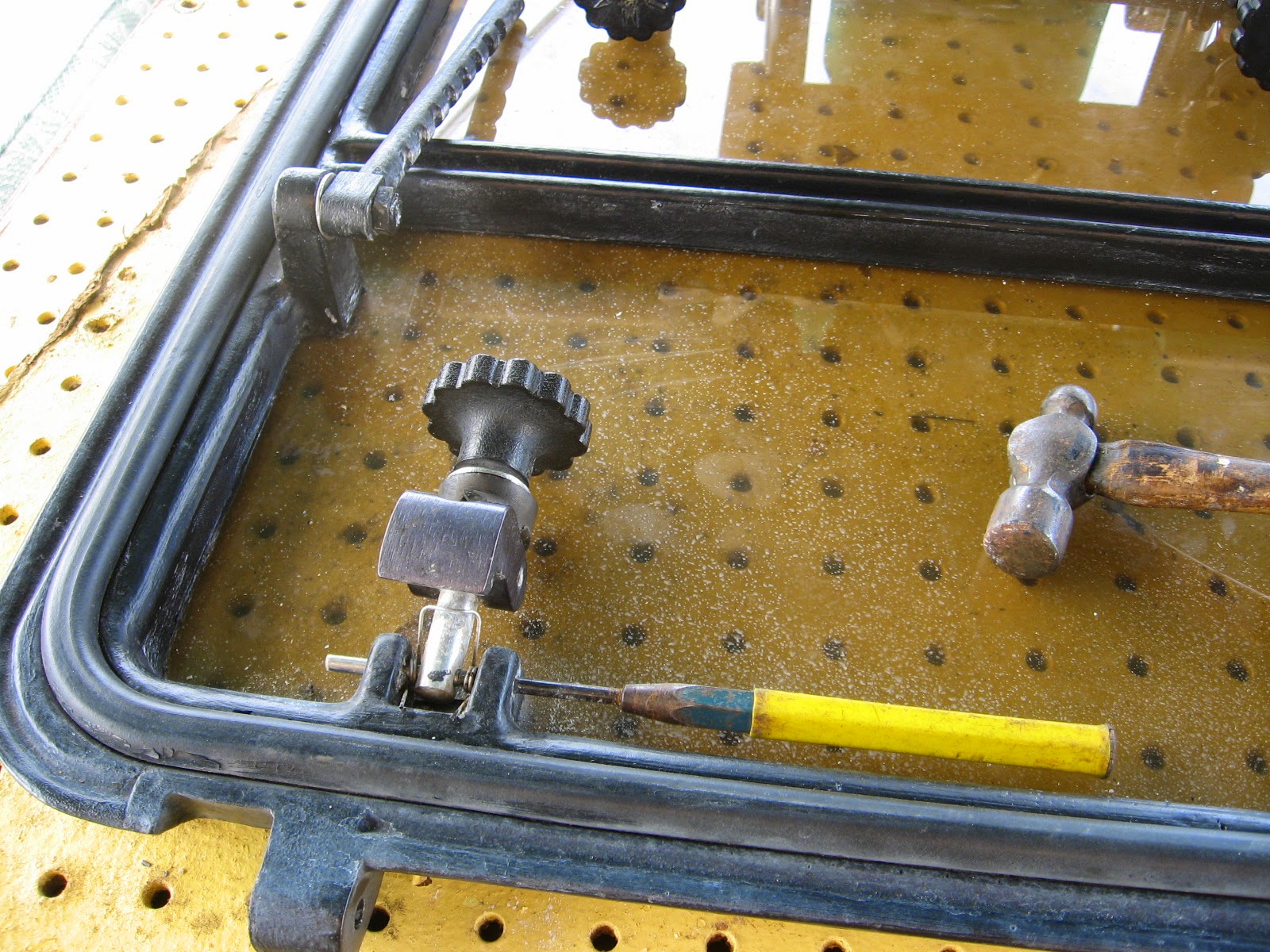
The dogs came out just as easy with an 1/8" punch and small hammer.

Very simple construction, a shaft, a dog, couple of pins and a tightening nut.
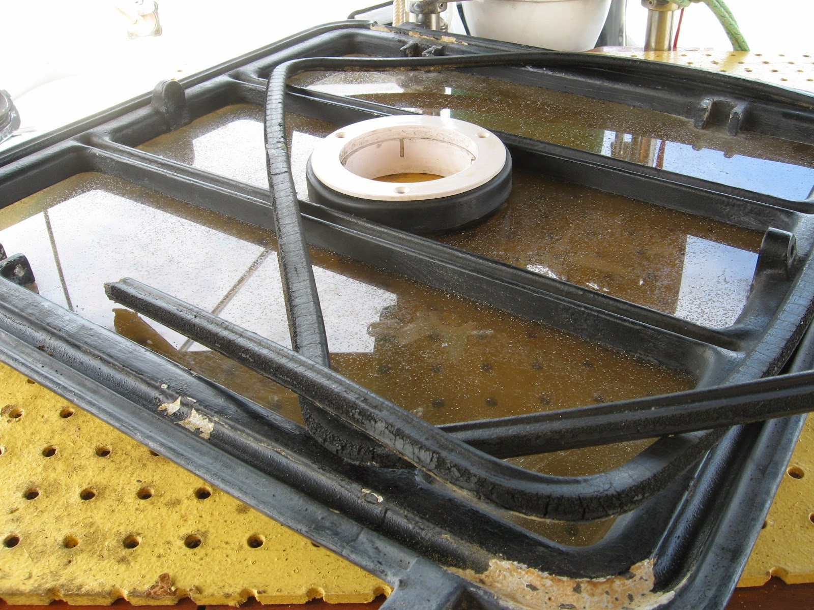
Old dry gasket material just as easily came right out.

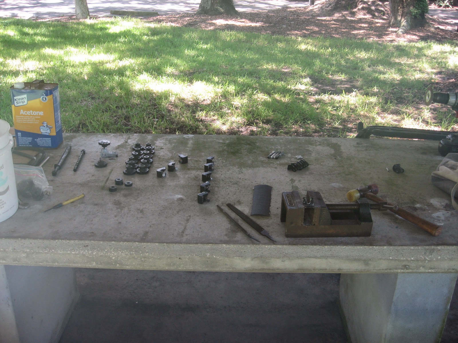
Lots of wire scraper, wire brush and sandpaper cleaning of all surfaces inside and out, it's kinda therapeutic for me, I just love making things better!
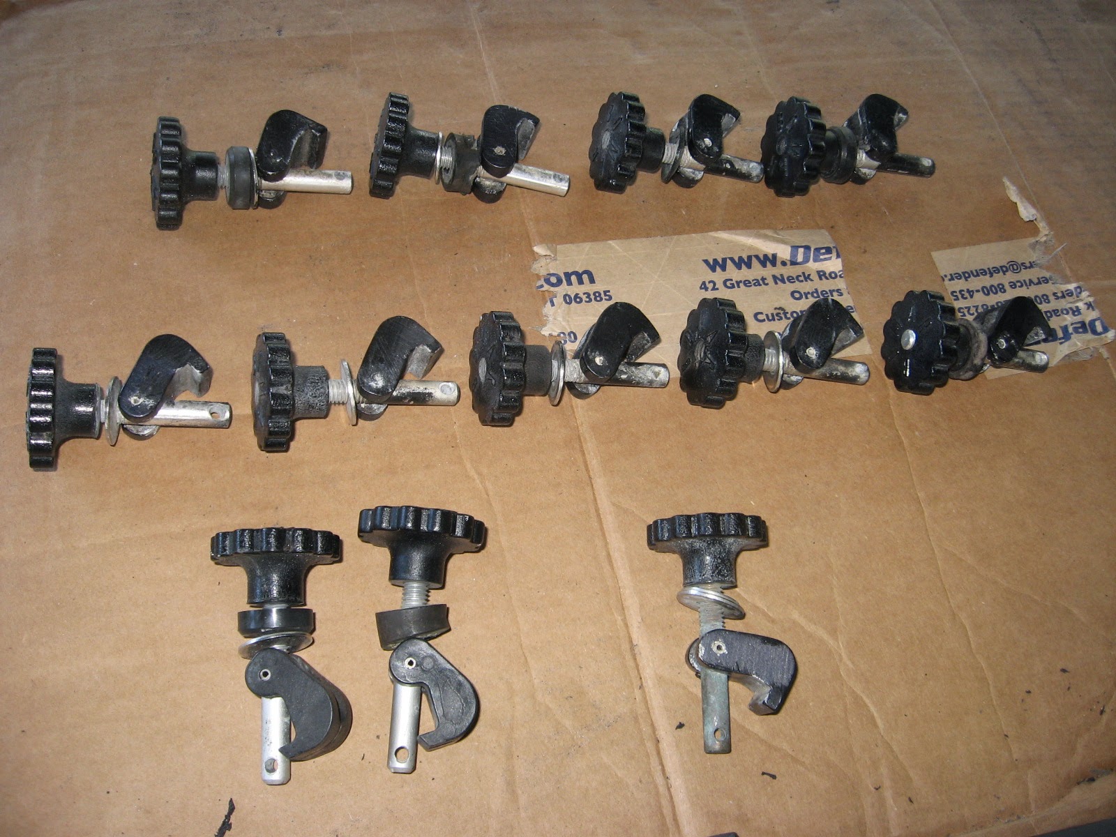
Sorting through all the dog downs, deciding what is worth keeping and or repairing and how many "new" complete kits to buy.
I filed and tuned up most all the dogs, had to make a few new shafts with material I had at hand ...

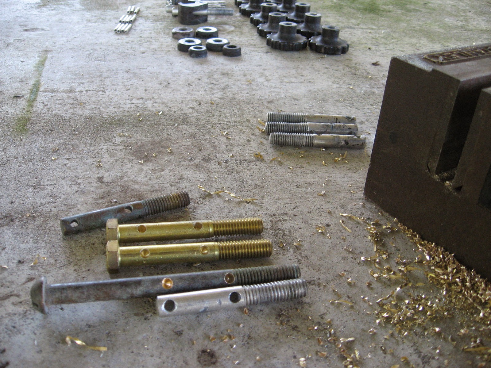
... to give me one hatch with 4 new bronze and brass studs, one hatch with original aluminum studs that were in good condition and one hatch with all new kits at $35 a kit. That's the one in the galley, used the most.

Using an old lens re-cut for more clearance, with a router I traced the new stock for a proper fit.
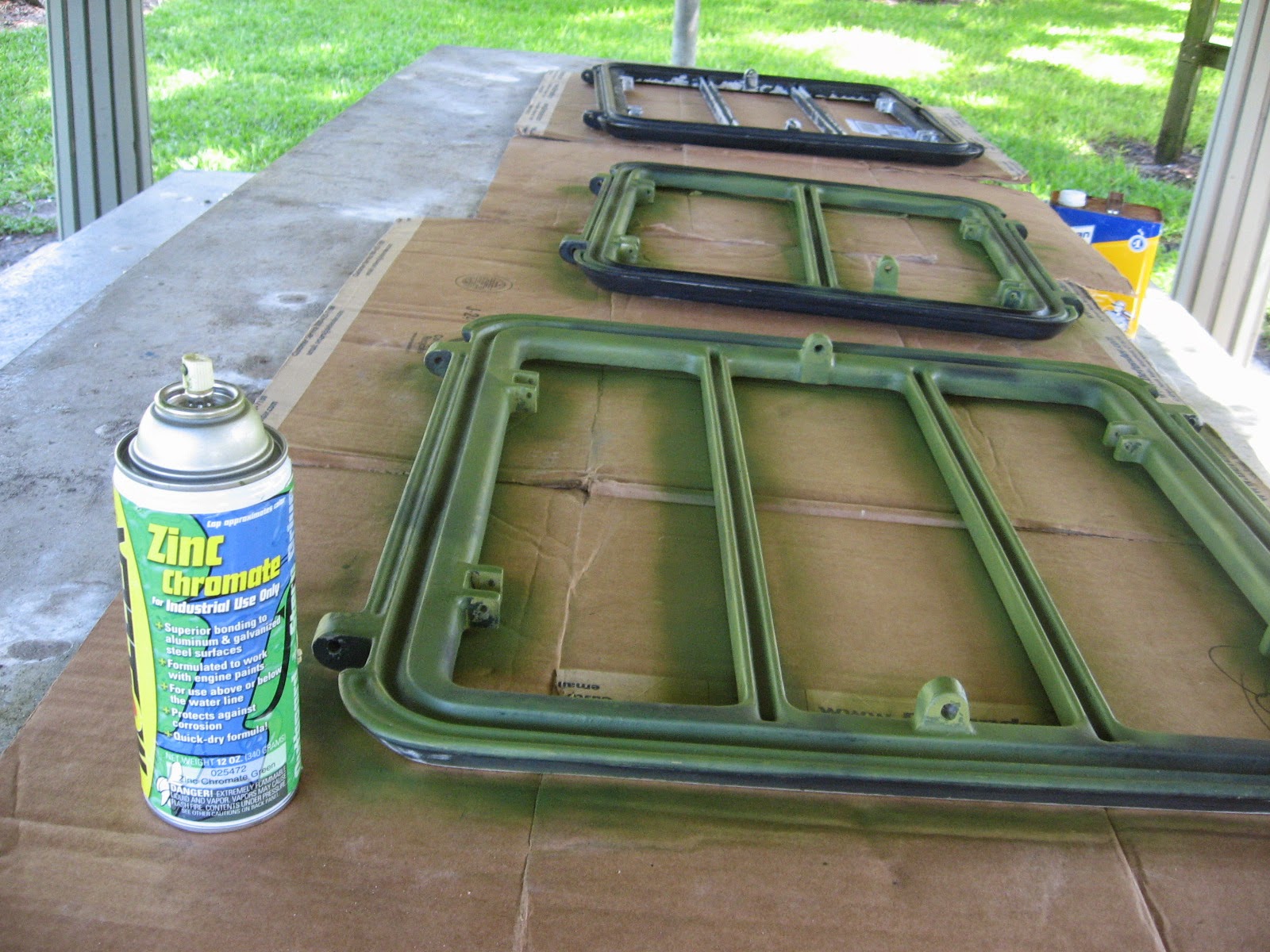

Zinc Chromate for the bare aluminum and a couple of coats of paint, let dry for a few days and...

... mask everything then...clean, clean and be careful of even your fingerprints as handling the new lens ...

... lay on the goop for a waterproof shiny new hatch.
I didn't get any pictures of laying in the new gasket. it went simple enough after a thorough cleaning and then clamping the hatches in place for a couple of days.

A total of about $100 per hatch, what's not to love about that?
After seeing the replacement cost of these old style offshore hatches we actually went and bought three, one step down, Bomar replacements for just over a $1000. After getting the new ones back to the boat we took a closer look at them side by side with the old ones. Wow! We brought the new ones back for a full refund. Let's keep the old ones and rebuild!
Once started, the old lenses came right out. A couple of these were leaking and it seemed to me that the lens were at one time cut too big and not given enough room to expand and contract. Should be (I think) about an 1/8" per foot of lens, 2' hatch=1/4". Google it, find out for yourself.


The dogs came out just as easy with an 1/8" punch and small hammer.
Very simple construction, a shaft, a dog, couple of pins and a tightening nut.
Old dry gasket material just as easily came right out.
Lots of wire scraper, wire brush and sandpaper cleaning of all surfaces inside and out, it's kinda therapeutic for me, I just love making things better!
Sorting through all the dog downs, deciding what is worth keeping and or repairing and how many "new" complete kits to buy.
I filed and tuned up most all the dogs, had to make a few new shafts with material I had at hand ...
... to give me one hatch with 4 new bronze and brass studs, one hatch with original aluminum studs that were in good condition and one hatch with all new kits at $35 a kit. That's the one in the galley, used the most.
Using an old lens re-cut for more clearance, with a router I traced the new stock for a proper fit.
Zinc Chromate for the bare aluminum and a couple of coats of paint, let dry for a few days and...
... mask everything then...clean, clean and be careful of even your fingerprints as handling the new lens ...
... lay on the goop for a waterproof shiny new hatch.
I didn't get any pictures of laying in the new gasket. it went simple enough after a thorough cleaning and then clamping the hatches in place for a couple of days.
A total of about $100 per hatch, what's not to love about that?
Tuesday, October 14, 2014
Navigation Station Redesign
John continues spiffing up his Catalina 30, s/v Dulcinea. Today, his project is a complete redesign and rebuild of the nav station. This project may be pushing the limits of what a "small" boat project is, but it is so chock full of goodies that I knew you'd want to see it!
There were a few things I didn't like about the Navigation Station.. First, the angled desktop kept everything on it sliding down, and sometimes to the floor.
there was also no place to mount the VHF radio except to the aft side, vertically.
the VHF radio mounted on the aft side of the station... this pic is taken looking down
Also, I want to eventually move all of the electrical panels to the Navigation Station, a more logical and safer location in my opinion, than the current location on the aft bulk head, where the backs of the panels are exposed to the Lazerette, albeit under the line locker, but I think it is possible that things could shift in there and come in contact with the panels, possibly shorting things out, or worse. currently there is no place to put the panels at the nav station.
Not a great place for electrical panels... the back side is open to the Lazerette, and is near the sinks.... oh, and see the round instruments on the far right? that is the engine hours and fuel tank indicators.... REALLY inconvenient, have to bend over the stove to read them! What genius thought that would be a good place?
Sooooooo, A redesign of the station is in order. First step. some boat Yoga to yank it out!
This is the downward-jam-yourself-into-small-spaces Boat Yoga position
My Brother-in-law removes the retaining board.
Halfway out!
Gone! Yuk! 37 years of dirt and grime under there!
When I dismantled the station, I discovered that the shelf that separates the top and bottom compartments was made out of Teak ply! Bonus! I will need this later to extend the vertical "Ears" to the bottom the deck! So I replaced this with a piece of Exterior Plywood.
Next, in my original design, I need to cut a Isosceles triangle out of the sides, but they had to be identical on each side... hmmm... ah! I stacked them (flush in the front), and then clamped them together. I will cut both sides at the same time! (Note I say the ORIGINAL design.... keep this in mind....)
Cut along the line with my trusty Jig saw....
here is a little trick when cutting out pieces like this... cut the first side, then put a clamp on top of that first cut, then cut out the second side.... this keeps the piece from flopping and binding the blade, not to mention from dropping to the floor after cutting the second side.
I was so happy with the way it turned out that rather than taking it back to the boat for a dry fit, I just sanded, patched, reassembled and refinished it! This was gonna be GREAT! I didn't even have to modify the desk top.... I thought I was going to have to cut some of it off! (ominous music plays here)
Doesn't this look great? Gosh I'm good!
So, being the happy camper I was, I put 6 coats of Varnish on the whole thing!
By the way, I agree with my friend Robert Salnick at WindBorne in Puget Sound on the subject of Painter's Points.... Get 'em and use 'em!
Then it was time to install it in the boat!! THIS is when I found out the FLAW in my design.... you see, I didn't account for the shelf on the right side of the Nav station.... see the fiddle on the desktop below? it is supposed to be an inch or so to the right, overhanging the edge of the nav station.....
Whoops! The desktop is supposed to be an inch further to the right.... the shelf blocks it!
see how the left side has a Big over hang and the right doesn't? This isn't gonna work....
Soooooo..... time for a redesign of the redesign. The first step was to remove the "ears" that weren't wide enough....
removing the ears using my Dremel Multi-tool
Then I created some cardboard templates that went from the bottom of the deck to the top of the nav station... Notice there is a channel that I had to work around on the bottom of the deck. Also notice these are MUCH wider than the original "ears"
the ear is cut off.... now for the other side....
Then I added a shelf to separate it into two sections, and to add some stability. I mounted blocks so I could attach the face plate. And what is that thing in the middle? Stay tuned!
The template laid out... remember the teak ply shelf I replaced? this is where I needed it!
Now to address that weird black spray painted thing in the middle.... Notice the location, just under the stereo. You see, my stereo connects via blue-tooth to my phone or Ipod, but I needed a place to put these when underway. So I made this little cubby hole. Put a little bit of anti-slip material in the bottom and Voila! It also is a great place to put pencils and pens too!
Building the top part of the Nav station. the area above the shelf is for the radios..
Now to take the newly fabricated top to the boat! This time I measured Many times, so all pretty much fit like a glove.
The Cubby hole for my Ipod and Phone (Ipod is in the cubby right now)
I needed a way to connect the upper and lower parts of the nav station, and not wanting to waste anything, I figured this was a good place to use the old ears!
YEA! Now the desk top fits like it is supposed to! WOO HOO..... no, wait a minute... Uh oh....
Darn it! I guess I am going to somehow modify the desktop..... It sticks out WAY too far.... More measurements, and take the desktop back home...
Looks great from the front!
Now I wanted to cut this desk top down, but I did NOT want to remove the fiddle rail, and I didn't want to chip the Formica top. So, I used some tricks I learned when renovating houses I have owned in the past...
First step is to put down painters tape so the cut line is in the middle of the tape.
Now, Normally you want to cut the counter top with the Formica side down, to virtually eliminate the chipping that will happen when it is cut. I could not do that in this case because of the Fiddle rails, so I had to cut it the other way..... MAKE SURE you use a Plywood blade on your saw (many 32 teeth per inch or better) AND have the blade just BARELY CLEAR the top. Then go SLOWLY.
Blade JUST clears the counter top
the Cut is complete
Since the blade didn't cut through the Fiddle rails, I finished it off with a hand saw...
Then it was time to hold my breath and remove the tape, to see how badly it chipped......
And, amazingly, not one single chip! Nice!
Finally I had to ease off the top corners so the desktop will open without binding. I used my trusty belt-sander for this. It made quick work of it!
and now I have a finished desk top..... back to the boat for the third time!!!!! while I was doing all this, I also made a door for the top part of the Nav Station, so now it was time to install them both!
The inside of the station, under the desk top
And so this Project draws to a close.... FINALLY! I have to find a way to make these posts a bit shorter, but this project was a big one.... I will cover the installation of the Radios and the associated wiring in a later post... this one has been long enough! But I am really happy with the results!
LOTS of storage in here... for now.
Coming up.... Installing the radios (it will be a shorter post! LOL)
What'cha think?
Till next time!
JEM


Subscribe to:
Posts (Atom)


