This exposed solenoid always bothered me. Non-AYBC compliant, non-USCG compliant, and a short looking to happen, the backside of this anchor windlass breaker has high-amperage exposed terminals.
I fabricated this simple cover from 0.09-inch FRP (the same materials I used for the window covers. Cut by score-and -snap, trim with disk sander, fillet corners with Epoxy + colloidal silica, finish with orbital sander and paint. In stead of screws (holes would show), attach with 3M Dual Lock.
The finished product looks factory. I think I will be using a lot of Dual Lock during the AC installation.
Showing posts with label fiberglass. Show all posts
Showing posts with label fiberglass. Show all posts
Tuesday, May 17, 2016
Exposed Wiring
Over at Sail Delmarva< Drew cleverly fabricates a cover for some exposed wiring...


Tuesday, February 9, 2016
A positive outcome and new skills!
Mike and Rebecca, living aboard s/v Zero to Cruising... No wait! ZTC is for sale! And Mike and Rebecca now live and cruise on s/v Frost, an Amel 53! Well, because it is a new boat for them, there will inevitably be new projects. Here is one - replacing a rusted out hawsepipe... and like the best of projects, completing it gives not only a feeling of satisfaction, but a new skill set...
There are not too many jobs on a boat that end up being easier or quicker than you initially estimate. In almost every case, it’s the exact opposite, and so it was with the project we’ve been working on for just over a week.
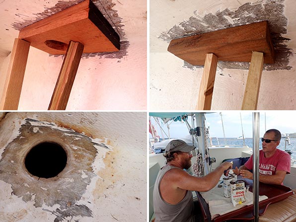
It all began with a bit of a rust stain on the exterior of our starboard bow. Inspecting the stain led us to the source, the old rusty hawsepipe in the starboard bow locker. The pipe, which the anchor chain passes through between the windlass and the chain locker, had pretty much reached the end of its lifespan. The exterior fiberglass was cracked in numerous places, and further inspection led me to find that the pipe that was inside it, made of iron I believe, was rusted and crumbling to pieces.
The old hawsepipe was the source of the rust on our hull.
Where as I had initially hoped that I could simply patch over the fiberglass, it now seemed obvious that the only proper way to fix it would be to cut the old pipe out and begin anew. Our friend Ken, who came over to offer his opinion on the job, assured me that he’d be available to help me through the steps. As the days went on, oh, how I bet he regretted that offer!
Of course, while we were at it, why not reinforce the anchor windlass to better deal with our new big Mantus anchor? It’s just a bit more work, right?
First using hammers, chisels and brute force, I removed as much of the old pipe as I could. Later, having borrowed Ken’s angle grinder, I was able to cut the remainder of the pipe and fiberglass out.
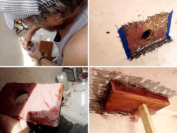
We puzzled over what to use to replace the old pipe. Stainless would be awesome but way too costly for such a job. I had read of one Amel owner who used PVC. As it turns out, some friends of friends had on hand a 3 foot length of 3″ diameter fiberglass tube that they no longer had a use for, perfect for our application! Huge thanks to s/v Virtue and Vice for passing that along to us!!!
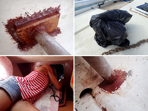
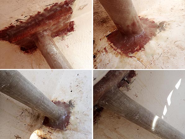
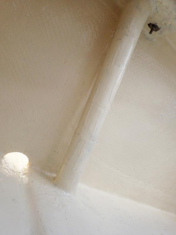
The photos below illustrate the steps that we went through. The mahogany backing blocks for the windlass, donated and shaped by Ken, were first attached to the top of the lockers using thickened epoxy. The pipe was cut to length and then also fastened in with epoxy, both from inside the locker, and from the underside, accessible from the chain locker. Later, the entire thing was glassed over. I also took the time to add a couple of extra layers of fiberglass cloth to the pipe, adding to its thickness to hopefully give it a few more years of wear.
On that note, will the pipe wear out? Undoubtedly. I’m confident it won’t happen quickly though, and when it does, it will be easy to repair. I’m pretty happy with how the job turned out, and even better, I learned a lot about this type of work from our friend. A positive outcome and some new skills… you can’t beat that.
Waiting for the paint to dry so that we can add a second coat.


Tuesday, January 12, 2016
Fender Washers--Basically Useless?
Drew has been at it again... Here he is testing fender washers as might be used instead of proper backing plates for items thru-bolted on deck. Drew made two posts; I have included both of them here.
In the process or researching an article on backing plates, it seemed worthwhile to actually test some washers. After all, it was the failure of fender washers that led to cracking of my deck and the need to remount the winches.
I used a 3/4" pine board as a surrogate for a cored deck and tightened a collection of 1/4" washers untill the first damage to the wood, and until failure. To no surprise, common washers, fender washers, and HDPE were glaring failures, and FRP and thicker metal washers were fine.
(click to enlarge table)
And then there is always the matter of what happens in wet places. Though I like aluminum for ease of fabrication, I also know its limitations.
As ramp-up for some Practical Sailor testing, I thought I would share a preview.
First, unable to secure scraps of deck material for which I could be sure of the pedigree, I laid up some of my own. The testing will based upon 1/2-inch balsa core with (1) 6-ounce cloth and (1) 17-ounce biaxial layers on the deck side and (1) 17-ounce biaxial layers on the under side.
I drill a 1/4-inch hole (no epoxy plug, block of wood on the back side) and tightened down a fender washer against it. At 10 in-pounds (about 675# load) the washer had distorted and the laminate was failing. for comparison, the bolt working load of a Lewmar 40 winch (1/4-inch bolts) with a strong grinder is about 500 pounds each. In other words, without an epoxy plug the bolt will fail under working load and standard ASME bolting load, with no safety factor for aging and fatigue. It is about 5x weaker than good design suggests. It also explains why I had a PO installed winch rip out.
By 18-in-pounds the fender washer was buckled and the nut was well into the core. For comparison, this is about 50% better than a plain pine board in each case.
I repeated the test with only lock washer. The same result! The fender washer resulted in no increase in strength. The point being, that the bolting washer provided better support in close, the end result being the same.
Testing for the actual project will involve proper epoxy plugs. However, since under the load the bolt will NOT be supported on the other side (the winch or cleat will be lifting) in the real world, the top side support will be supplied by a 4-inch diameter ring spacer, allowing the washer to pull through, if that is what it wants to do. I've tested this without the epoxy plug; not surprisingly, it lowers the failure load and creates top side damage much like I saw on my failed winches.
We'll see. But for now, the moral of the story is that fender washers are basically useless; they fail as soon as they are actually needed.


Tuesday, October 13, 2015
How To Make Holes In Your Boat
Making a hole in your hull is serious business, even more so if your hull is foam-cored. Jeff and Anne aboard s/v Pilgrim and in the midst of a complete refit demonstrate how it should be done...
We have added two new 1-1/2” thru-hulls above the water line. The port thru-hull will serve as the discharge for the upper, larger capacity bilge pump (3700 G/H).
The starboard side thru hull will act as a drain for the deck scupper. We did not like the long hose run from the starboard scupper to the torpedo tube drain manifold. We also wanted to rig a method for collecting water off the deck if necessary.
Prior to drilling any holes we assembled the new starboard deck drain plumbing.
Test fit of new plumbing for starboard deck drain. Note old drain hose at far right. Test fitting the new plumbing allowed us to accurately mark the location for the starboard thru hull. The port side fitting connects to a single flexible hose so identifying the exact location was less critical.
Since the location of the holes was marked on the inside of the hull, I began the drilling using a ¼” bit to drill a pilot hole from the inside out. The ¼” hole matches the diameter of the hole saw pilot bit. Next, I chucked a 1-7/8” hole saw into the drill and moved outside the hull. Drilling the larger hole from outside allows for properly aligning the hole perpendicular to the hull and creates less dust inside the boat.
We drilled two 1-7/8" holes in the hull. The Morgan 382, 383, & 384 hull’s have a foam core above the waterline. This is the first time we have drilled large diameter holes above the waterline and subsequently our first look at the coring material.
Close up of plug offers a glimpse of Morgan's construction techniques. The hull is slightly over one inch thick… the outer fiberglass layer is 5/16”; the foam 9/16”; and the inner fiberglass layer 1/8”Placing holes in cored hull’s or decks requires additional effort to ensure water never reaches the core material. In smaller, fastener sized, holes this can be achieved by over drilling the size of the hole and then filling it back with epoxy. Larger holes for plumbing fixtures require a different approach.
Using a small flat screw driver and a couple different styles of picks, we removed all the coring material within approximately ½” of the hole.
Foam core removed from the area around the hole. The plan is to fill the newly created void around the hole with thickened epoxy. So the next couple steps are the usual epoxy prep… 80 grit sanding, acetone wipe down, mask area... We used a syringe to apply the epoxy and a plastic spreader to achieve a nice clean finish.
Filling the area around the hole with thickened epoxy. After a couple days for the epoxy to fully cure, we returned to the project. Using a #49 cabinet rasp and some 80 grit sand paper, Anne cleaned up any excess epoxy from the holes. While I cut down the length of the threaded section of the thru-hull to properly fit the valve on the starboard side.
Prior to applying any sealant we dry fit the two thru-hulls and masked the surrounding area. For the final install we used 3M 5200 sealant. Anne worked the interior and I the exterior.
New thru hull fittings are just above the waterline and five feet forward of the torpedo tube drain on either side of the hull. We are still waiting on hose to connect the bilge pump to the new fitting on port, but we wasted no time installing the new starboard deck drain plumbing.
New deck drain w/ option for filling water jugs installed. Since the installation we have weathered a couple heavy rains. The starboard deck scupper is performing much better with the new system.
What was that you said?
Why yes that is a new battery selector and bilge pump switch panel in the image above. I’ll post more info on that project very soon.


Tuesday, September 15, 2015
New Shelf for the Cockpit Locker
Jeff and Anne continue the complete refit of s/v Pilgrim. Adding organization to the storage in the cockpit locker is a part of that refit...
Adding a shelf outboard along the hull in the cockpit locker will provide some additional storage possibilities and a platform on which to mount the refrigeration compressor.The fore end of the shelf will rest upon the top of the new bulkhead.
Test fit of new 1/2" plywood shelf in cockpit locker. Tabbing a ½” plywood panel to the upper, aft interior of the cockpit locker (upper, left in image above) allowed me to easily attach a bracket to support the aft end of the shelf.The shelf will be tabbed to the hull along the outboard side thus another round of grinding to expose the fiberglass hull.
Pile of gel-coat and fiberglass dust after grinding to expose bare fiberglass. YUCK! I am eager to be done with grinding fiberglass inside the boat. It creates a huge mess and fine dust spreads throughout the interior.We created the new shelf using the 1/2” prefinished birch plywood.
Unfortunately the nice finished surface must be ground off in the areas receiving tabbing.
48" run of 1708 cloth tabbing between the hull and the new cockpit shelf.
For people familiar with the M382, yes, this photo was taken from below the helm seat.We installed a 48” X 6” strip of 1708 cloth . The tabbing stiffens and strengthens the shelf significantly.Next, we applied two coats of primer and two coats of paint to the shelf and the upper sections of the cockpit locker.
Ahh... the satisfaction of fresh, unmarred paint. Our plan is to mount the refrigerator compressor near the aft end of the shelf. Then install one maybe two vents in the cockpit side wall to provide the unit with fresh air. The forward end of the shelf will store cleaning, maintenance, misc supplies in plastic bins. To keep the plastic bins in place while the boat heels we added a tall fiddle along open face of the shelf.
Teak fiddle installed on the shelf and deck drain hose secured to underside of shelf. Next up is installing the engine access panels and plumbing the lower and middle bilge pump discharge hoses to the drain manifold.
More images and notes from this on-going project are available in the Cockpit Locker Refit Photo Album


Tuesday, September 8, 2015
Glass-Bottomed Dinghy
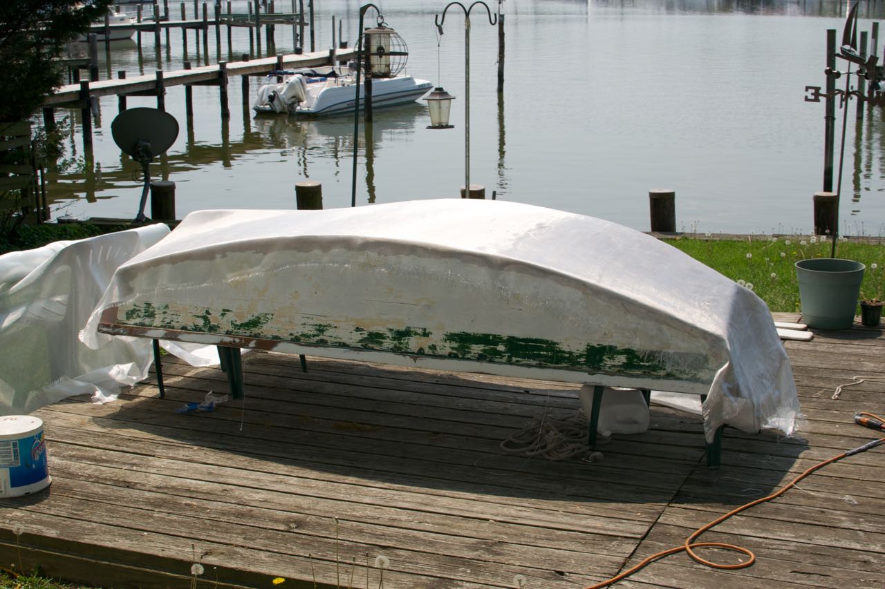
Over on s/v Cay of Sea, Rick and Ruth go to work sheathing their dinghy with fiberglass. Why do this? Well, it is a way to extend the life of a wood dinghy, and the fiberglass takes running up on sand and gravel much better than does wood.
[Editor's note: for those of you that have not worked with epoxy, as it cures a substance is pushed to the surface, called the "amine blush". If this is not removed before anything else is applied, it prevents a bond from being made.]I filled more small splits with peanut butter-consistency epoxy on the bottom today. These are super small splits – just narrow cracks – I forced epoxy into them with a putty knife, filling with cross-grain motion, then scraping up excess with the grain. Had I prepped the bottom for glass and resin, I could have gone directly to sheathing without waiting for resin cure. But I didn’t think it through, and needed to solvent wash the surface first and grind a few patches of cured epoxy. After letting the crack fills cure, I finished the prep.

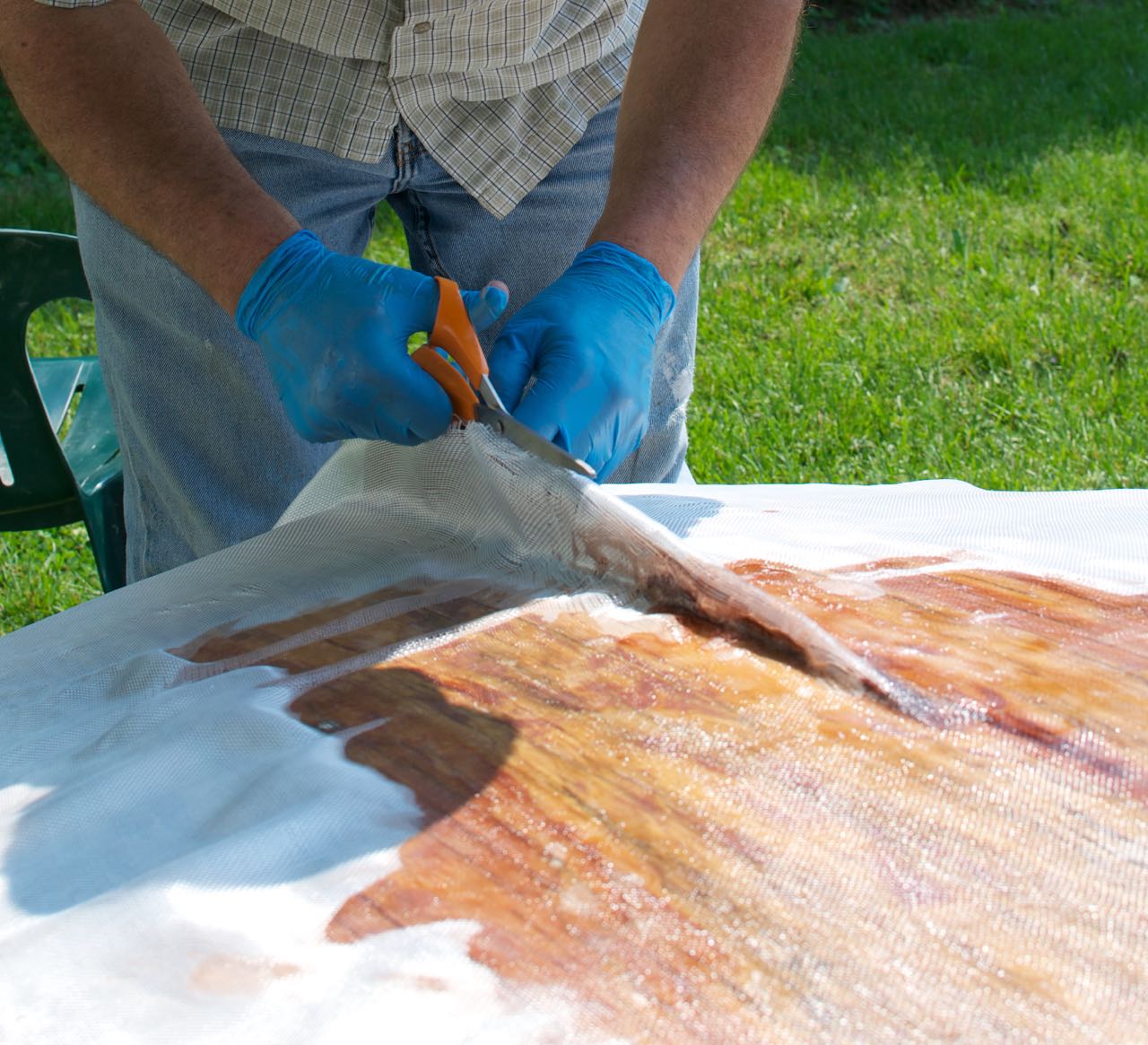
Draping the glass over the bottom showed me where to trim the excess, and where likely relief cuts were going to be needed: at the keel, in the corners, and a couple of places on the transoms I didn’t anticipate. It’s easy to push the weave of the fabric around while it’s wet, but care has be taken to keep pockets of void from pushing up as a result. Relief cuts are the best way to get the fabric to lay flat.
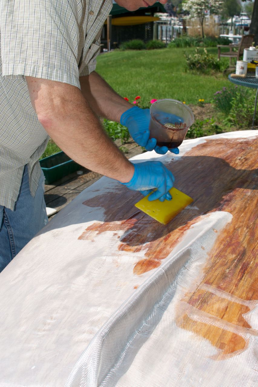
A large squeegee or putty knife/scraper is the best tool for wetting out on horizontal surfaces. It was a beautiful day – about 70 degrees – but the sun shining on dark surfaces made them warm, and consequently the resin set up pretty quickly. I had ample time to wet out each section, but I still had to move quickly. I spread out the resin and thoroughly saturated the weave, then quickly replenished my resin container. Three pumps each of resin and catalyst provided just the right amount to spread at one time. I used about 20 ounces of resin and catalyst to saturate the whole surface, including transoms.
I switched to a chip brush for the transoms and turn of the bilge, as pouring the resin wasn’t going to work on vertical surfaces. After an hour’s steady work, the entire surface was done and beginning to cure in the sun. I’ll do an additional coat tomorrow (or next time, depending on weather). One more coat will serve to completely fill in the weave pattern of the fabric, and provide a smooth surface. When I removed the boat from its elevated supports, I could readily feel the increased rigidity the glass and epoxy provides. The transoms will get even more rigid when I glass their inside surfaces.

Tuesday, June 30, 2015
Corners
This post originally appeared on Windborne in Puget Sound
Have you ever done fiberglass layup? If you have, then you know how difficult it is to get the wetted cloth to follow a sharp outside corner tightly, with "sharp" being a variable depending on how heavy the cloth is. It tends to spring back, leaving a gap underneath.
Well, boat manufacturers have the same problem you do. And on Eolian, there was a place where the cloth pulled away from the gelcoat-sprayed mold corner, leaving a gap between the gelcoat and the cloth. This revealed itself over the years by the gelcoat cracking up in the bottom of what was now an inside corner, because it was unsupported.

The problem area was on the aft deck, where the coach house meets the deck. Sadly, I did not take a "before" picture... but this one shows the extent of the area to be repaired after I ground out all the loose gelcoat flakes with my trusty Dremel tool (the perfect tool for this job!).
Now, gelcoat is formulated for application by spraying. That means that it is quite fluid, tho the thixotropic agents included mean that when you stop disturbing it, it stays put (unlike epoxy, which continues to run and drip, seemingly forever). But that fluidity makes it quite difficult to control the application accurately. I mixed the gelcoat in a small cup with a tongue depressor and then used that same tongue depressor as an applicator - the radius of the end was close to the radius of the inside corner of the repair area, if I tilted the stick at the right angle.
After the gelcoat had gone off I sanded it using 220 grit wet/dry sandpaper (wet), a small piece wrapped around the end of another tongue depressor, to knock down the areas that needed to be flat. For the radius in the corner Jane donated an old Chap Stick container, which turned out to be a pretty close fit. Sanding is tricky. You want to knock down the high spots and get nearly level with the surrounding area, but you don't want to cut flush until you are working on the final coat. The original gelcoat, tho much thicker than a paint layer would be, is quite thin and easily sanded thru. So you only want to sand flush once.
Because of the fluidity of the gelcoat, it took several applications to get the surface brought up (oh, how I wish that there was a gelcoat formulation even as stiff as, say, Greek yogurt!). In the beginning I applied a lot, but at the end just a dab here and there to fill the hollow spots.
For final finishing I went over the area with 400 grit wet/dry (wet), and then used some polishing compound. It comes out as shiny as a factory finish.
Again, major kudos to Fiberlay for such an amazingly perfect color match. If you can see any color difference at all in the picture, it is because in the area where I was working the oxidized gelcoat got cleaned off, brightening the color.
(And yes, replacing that fixed port is on the list.)
Have you ever done fiberglass layup? If you have, then you know how difficult it is to get the wetted cloth to follow a sharp outside corner tightly, with "sharp" being a variable depending on how heavy the cloth is. It tends to spring back, leaving a gap underneath.
Well, boat manufacturers have the same problem you do. And on Eolian, there was a place where the cloth pulled away from the gelcoat-sprayed mold corner, leaving a gap between the gelcoat and the cloth. This revealed itself over the years by the gelcoat cracking up in the bottom of what was now an inside corner, because it was unsupported.

The problem area was on the aft deck, where the coach house meets the deck. Sadly, I did not take a "before" picture... but this one shows the extent of the area to be repaired after I ground out all the loose gelcoat flakes with my trusty Dremel tool (the perfect tool for this job!).
Now, gelcoat is formulated for application by spraying. That means that it is quite fluid, tho the thixotropic agents included mean that when you stop disturbing it, it stays put (unlike epoxy, which continues to run and drip, seemingly forever). But that fluidity makes it quite difficult to control the application accurately. I mixed the gelcoat in a small cup with a tongue depressor and then used that same tongue depressor as an applicator - the radius of the end was close to the radius of the inside corner of the repair area, if I tilted the stick at the right angle.
After the gelcoat had gone off I sanded it using 220 grit wet/dry sandpaper (wet), a small piece wrapped around the end of another tongue depressor, to knock down the areas that needed to be flat. For the radius in the corner Jane donated an old Chap Stick container, which turned out to be a pretty close fit. Sanding is tricky. You want to knock down the high spots and get nearly level with the surrounding area, but you don't want to cut flush until you are working on the final coat. The original gelcoat, tho much thicker than a paint layer would be, is quite thin and easily sanded thru. So you only want to sand flush once.
Because of the fluidity of the gelcoat, it took several applications to get the surface brought up (oh, how I wish that there was a gelcoat formulation even as stiff as, say, Greek yogurt!). In the beginning I applied a lot, but at the end just a dab here and there to fill the hollow spots.
For final finishing I went over the area with 400 grit wet/dry (wet), and then used some polishing compound. It comes out as shiny as a factory finish.
 |
| And done. |
Again, major kudos to Fiberlay for such an amazingly perfect color match. If you can see any color difference at all in the picture, it is because in the area where I was working the oxidized gelcoat got cleaned off, brightening the color.
(And yes, replacing that fixed port is on the list.)
Tuesday, May 26, 2015
I wonder if you knew
This post is a mash-up of two posts that originally appeared on Windborne in Puget Sound
Say you have a boat, and say that the gelcoat has some flaws in it (but then I repeat myself). These might be caused by say, a dock that approached too quickly, or perhaps a wayward buoy inconveniently located right on your waypoint. Never fear... you don't have to live with those flaws.
Gelcoat is simply polyester resin with pigment and some flow modifiers added to it - there is nothing magic in it. The magic *is*, however, in getting the right mix of pigments so that it matches the gelcoat on your boat. You can do this (I have), but it is a truly tedious process and, for me anyway, very very challenging. Instead, I have an alternative for you.
I wonder if you knew that Fiberlay will make up a quart (minimum size) of gelcoat to match your sample. They scan the sample using not one, but three different light sources, take the average of those three results, and use that as a starting point for a manual match. You even get a custom label!
The cost is surprisingly reasonable: $73 tax included. That compares to a quart of off-the-shelf Interlux Brightsides urethane paint which pushes $50 pretty hard. Not bad at all.
Now, here's the tricky part - how do you get them a sample to scan? If you have something that can be taken off your boat that has representative gelcoat on it (a lazarette hatch for example), then you are in good shape. If not, then I hope you have saved all those plugs you cut out when installing instruments, etc.
But even failing that, for an additional charge, Fiberlay will send a technician to your boat to do the scan - but I expect that the additional charge is not necessarily trivial, skilled labor being the most expensive commodity in today's world.
Next, you will have a choice to have the gelcoat mixed up with or without wax.
Wax? Why wax?
You see, oxygen is a chain stopper for the polymerization reaction that turns liquid polyester resin into solid polyester resin. That means that the surface of a gelcoat application will not cure where it is exposed to air. When you are making a boat in a female mold, this is a good thing, insuring that the next layer to be applied will bond chemically with the uncured surface of the gelcoat. When patching this can be handy too, especially since gelcoat shrinks some while curing, and thus will likely require more than one application to a given patch.
But eventually, you will want the final layer to cure. That's where the wax comes in. If the gelcoat has wax mixed into it, the wax migrates to the surface as the cure progresses, sealing off the surface from the air and making a complete cure. This is what you would want if, for example, you were spraying gelcoat onto a finished lamination on a male mold. Or if you were willing to scrupulously dewax the surface before applying another layer of gelcoat.
I chose to have the wax left out. And I bought a small bottle of PVA (polyvinyl alcohol). This is a water soluble plastic that can be painted over the final layer of gelcoat to exclude air from the surface. A simple water rinse removes it.
So, how did it turn out? Here you go:

Yes, there is a little bit of white showing on the edge chip where I failed to remove enough of the Previous Owner's MarineTex patch. I will grind it out and apply more gelcoat. Again, a process I am way too familiar with...
But the color match is absolutely perfect! Huge kudos to Fiberlay for a match well made!
Gelcoat is simply polyester resin with pigment and some flow modifiers added to it - there is nothing magic in it. The magic *is*, however, in getting the right mix of pigments so that it matches the gelcoat on your boat. You can do this (I have), but it is a truly tedious process and, for me anyway, very very challenging. Instead, I have an alternative for you.
I wonder if you knew that Fiberlay will make up a quart (minimum size) of gelcoat to match your sample. They scan the sample using not one, but three different light sources, take the average of those three results, and use that as a starting point for a manual match. You even get a custom label!
 |
| (Pay no attention to the gelcoat smeared on the outside of the can, and don't let the can fall out of your car onto the pavement - the lid will probably come off) |
Now, here's the tricky part - how do you get them a sample to scan? If you have something that can be taken off your boat that has representative gelcoat on it (a lazarette hatch for example), then you are in good shape. If not, then I hope you have saved all those plugs you cut out when installing instruments, etc.
 |
| Always save those plugs |
Next, you will have a choice to have the gelcoat mixed up with or without wax.
Wax? Why wax?
You see, oxygen is a chain stopper for the polymerization reaction that turns liquid polyester resin into solid polyester resin. That means that the surface of a gelcoat application will not cure where it is exposed to air. When you are making a boat in a female mold, this is a good thing, insuring that the next layer to be applied will bond chemically with the uncured surface of the gelcoat. When patching this can be handy too, especially since gelcoat shrinks some while curing, and thus will likely require more than one application to a given patch.
 |
| PVA |
I chose to have the wax left out. And I bought a small bottle of PVA (polyvinyl alcohol). This is a water soluble plastic that can be painted over the final layer of gelcoat to exclude air from the surface. A simple water rinse removes it.
So, how did it turn out? Here you go:
 |
| Filling some screw holes and chips on the edge of a cockpit seat |
Looks pretty good, doesn't it? I must say that managing the gelcoat as you are applying it is difficult. Just like working with polysulphide, it seems to get on everything, including my hands, my pants, and my feet. You will want to keep a can of acetone and a rag handy.

Before I applied it to the problem areas, I used my Dremel tool to clean them up. Some were just small screw holes or chips as in the picture above, but one area needed severe remedial work. I mixed the gelcoat in a plastic cup with a tongue depressor and then used the tongue depressor to apply it. On the next batch I think I will try a paint brush for the larger areas - the stuff is pretty runny.
After it goes off, it needs to be sanded, a process I am way too familiar with from doing automotive body work. I used 220 grit wet/dry paper, wet, and I applied blue tape around the area to be sanded so that I wouldn't accidentally sand thru the gelcoat on adjacent areas. Once I had the patch down to about the thickness of the tape I switched to 400 grit, removed the tape, and sanded it flat. Then a touch of polishing with some compound, and...
 |
| Poof! Gone! |
But the color match is absolutely perfect! Huge kudos to Fiberlay for a match well made!
Tuesday, May 12, 2015
Molding A Semi-Circular Fiberglass Conduit
Aboard s/v Pilgrim, Jeff and Anne continue what can only be classed as a keel-up rebuild. Most of what they are doing is not of a scale suitable to be included here (tho I have fudged a couple of times...). But this piece of work is.
And I did not know that about duct tape - thanks Jeff!
And I did not know that about duct tape - thanks Jeff!
When constructing the 25" long conduit running under the ice box ( see – January 17th Post) I used prefabricated, 1” thick foam core paneling. The paneling provided additional insulation under the box and the completed assembly added structurally to the hull by serving as a stringer between two transverse bulkheads.
The 5” long section of conduit running between the aft panel of the ice box and the new cockpit locker bulkhead does not need to provide additional insulation nor contribute structurally. It’s sole function is to provide a water tight passage way under the ice box insulation. Thus I chose a quicker and less costly method for building a conduit…
Save for some two-part epoxy all the components of the conduit fabrication are pictured Using a plastic, 1G jug and some duct tape I created a fiberglass mold for the section of conduit required.
The duct tape serves as a mold release agent and as part of the mold. I began by cutting the jug in half. To assist in maintaining the shape of the plastic ran one strip of tape across the open face of the jug. I then placed the jug on a board covered with plastic sheeting and covered it with duct tape. Epoxy will not bond to duct tape so it serves in place of mold release wax. The duct tape also allowed me to create a nice radius at the intersection of the jug and the base.
Test fitting the 1708 cloth on the mold. I then cut a section of 1708 cloth to cover the mold. One layer of cloth was adequate for my application, but additional layers could be added to create a load bearing conduit.
Time to walk away and let the epoxy cure. I then wet out the cloth and laid it over the mold and went home for the night.
Conduit fresh off the mold. The next morning I lifted the conduit off the mold. While wearing leather gloves I dressed the sharp, jagged edges by hand sanding with 35 grit paper then sanded the entire piece with 80 grit sandpaper.
fitting the conduit to the hull and bulkhead. I fit the piece in position and marked the excess material. The single layer of cloth cut easily with a jig saw with a metal cutting blade. I believe that tin snips would also work for shaping the piece. Fine tuning the fit was done using 80 grit paper on an orbital sander.
Conduit bonded to hull and bulkhead with thickened epoxy and cloth tabbing. Once satisfied with the fit, I used two small sections of fiberglass cloth to tab the base flanges to the hull. I sealed the fore and aft ends of the conduit to the adjacent bulkheads with a fillet of thickened epoxy.Now it is time to bury the conduit under layers of ice box insulation.
More images and notes from this on-going project are available in the Ice Box Rebuild Photo Album.


Subscribe to:
Posts (Atom)


