As I promised earlier, I'm writing up the autopilot repair in this separate post, now that we're safely anchored off Fort Macon, near Beaufort, North Carolina (map). I won't cover anything else here, so if you're not interested in the repair you can skip the remainder of the post.
By contrast, if you landed on this post from somewhere else, a little background is in order. Vector has a hydraulic steering system, with most of the components coming from the Canadian firm Jastram. That steering system includes a pair of big hydraulic rams that move the tiller arms and thus the rudder, two manual helm pumps operated by big 30"-diameter "destroyer-style" helm wheels, and an electric helm pump connected to an electronic autopilot. There are also two rudder feedback senders, one made by Jastram that drives an analog gauge on the helm console, and a second that is part of the autopilot system.
The autopilot is a Simrad unit common on boats of Vector's era, developed by Robertson, whom Simrad purchased before themselves being absorbed into Navico. Other than some water intrusion into the flybridge control head, the Simrad system has worked reasonably well since we got the boat, and we're quite happy with it. The main control unit, which nowadays would be called a computer but when this system was released was called a "junction box," a J300X model, has several output terminals to drive a variety of electric helm pumps, although Simrad also sold their own version. We have two control heads for the system, an AP20 in the pilothouse and the smaller AP22 on the flybridge.
There's really nothing at all wrong with the Simrad part of the system. It's an older unit and sometimes it misses or misconstrues NMEA inputs from the chartplotter computer, which tells it where to go in navigation mode, and when such an event starts to send us off in an odd direction we'll often say "go home, Otto, you're drunk." Typically, disengaging and re-engaging navigation mode is all that is required to get past these rare glitches.
The Jastram pump has also run more or less flawlessly until a week ago, when it quit briefly on our way into the Alligator river, and then again permanently while crossing the Pamlico the following day. Given its complexity, there are quite a number of ways in which it can fail, and several of those are electrical or electronic in nature. My first impulse was to start taking apart its integral electrical control box and put a meter on the various signals from the autopilot control unit to see if the commands were even coming through, or if either the thermal circuit breaker or the motor solenoid was not passing power through to the motor.
Motor end cap, full of carbon dust. You can see bits of the commutator in the dust.
That diagnosis revealed in short order that power was going to the motor but the motor was not turning, and removing the motor end cap, which can be done with the motor still attached, quickly revealed why: the commutator had disintegrated. The end cap was nearly packed full of dust from the carbon brushes, and I found bits of the commutator in the dust. Reluctantly, we diverted our course and put into port, hand steering for some eight hours or so.
The commutator end of the armature, still in the motor housing. You can see in-place commutator pads on the left, and missing spots on the right. And more dust.
After deciding to make port in New Bern, NC, I called three different electric motor repair places there. Upon explaining the problem, each told me the motor was not really repairable and would need to be replaced. Each also told me that without the specifications, they could not match anything up to provide a replacement motor. Thus started a lengthy Internet search for either a replacement motor, or an entire autopilot pump.
Some of the broken bits of commutator. No way to reattach these.
In the process of trying to source a motor and/or a whole pump, I learned a great deal about autopilot pumps in general and ours in particular. Now that I know it, it all makes perfect sense, but it's not something I had to think about before.
Our pump is a constant-running pump with a "shuttle valve" or "pilot valve" attached. When the autopilot is engaged, the pump runs continuously and in one direction only. Absent any commands, the fluid leaves the pump and immediately returns via a U-turn in the center of the pilot valve. When the autopilot commands right or left rudder, the shuttle moves in a corresponding direction to send the fluid into the helm lines leading to the ram cylinders in one direction or the other; from the point of view of the valve, this is either a "straight through" or "crossed over" arrangement of the output.
The cover plate from the shuttle valve, showing the fluid flow diagram.
When I started looking into replacement autopilot pumps, the vast majority on the market were not constant-running pumps with shuttle valves, but, rather, reversible pumps. The pump is plumbed directly to the steering lines, and the motor is operated in one direction or the other, by changing polarity, to move the rudder, which stops when there is no power sent to the pump at all. Unsurprisingly, these types of pumps, being much simpler in design, were considerably less expensive than the constant-running types.
Upon further investigation I learned that autopilot pumps, while often sold in catalogs based on boat length, are really sized instead by the volume of the steering ram(s). When you think about it, this makes perfect sense: the pump needs to be able to take the rudder from full left to full right in a set amount of time; 20 seconds is a typical number for automatic operation; half that or less might be required if "manual" steering will be done by means of a follow-up lever. How long it takes the pump to move the rudder is a function of the flow rate of the pump and the volume of the steering ram(s).
Vector has two steering rams with a capacity of 300cc apiece. That means that 600cc must flow through the system to move the rudder from full lock right to full lock left or vice versa. The Jastram pump installed with the system is a 3 liter/minute pump, or a lock-to-lock time of about 20 seconds. By contrast, the largest reversible pump I found, at around $900, was rated for 2 liters/minute, and pumps in the $500 range were more like 1 liter/minute. None of those was going to cut it with our system, and 3 liter/minute pumps, all of which are the constant running type with shuttle valve, are in the $3,000 range. Learning this gave me great incentive to repair the pump we already had.
Somewhere in the process of this research, I learned that a now-discontinued reversible pump, made by Accu-Steer, is the underpinning of our pump. Jastram partnered with Accu-Steer and mated a valve block and a Vickers shuttle valve to their HRP-75 pump to create the Jastram HPU-180 pump, then hard-wired the motor to run in a single, continuous direction. I was able to find a replacement HRP-75 on eBay (which I later purchased as a spare; we should have it in a couple of weeks) and deduce some things about the motor from a partial nameplate in the listing photo.
Between that, the physical characteristics of the existing motor and pump, and the limited specs in my owner manual, I guessed that a 1/7-HP rated motor turning around 1,700 rpm at 12 volts would be sufficient for the task. Motors of about this specification, but with square rather than round end-plates, are available on short notice from Grainger for about $270 or McMaster-Carr for about $190. In either case, I'd have to modify the mounts, but, more importantly, find a way to couple their 1/2" output shafts to the pump's 3/8" input coupling.
After hunting around for quite some time, I came across this motor available on Amazon for just $50 with free two-day Prime shipping. It's rated at 3,800rpm at 24v, or half that at 12v, with the required 150-watt continuous rating. It's significantly smaller physically than the motor it's replacing, which gave me pause, and I knew I'd have to find some way to mount it with its smaller end-cap, as well as adapt its 5/16" output shaft to the 3/8" pump input.
Old motor at left with new one at right. Note the machined lip on the old motor and the four mounting holes on the end cap; in this photo the new motor has already been drilled and tapped for the same mount and "machined" down to the same OD.
With a replacement pump/motor assembly on tap via eBay and nothing to lose, I ordered the motor on Amazon with a delivery for Tuesday afternoon. As soon as it arrived, I set to work. After a quick test to ensure the motor spun properly in both directions, I started on the output shaft adapter. This started out as a length of 3/8" OD, ~5/16 ID copper tubing, less than a dollar for 3" worth at the hardware store in town.
It's impossible to cut a clean end on soft copper tubing, so I had to run my 5/6" drill bit through the tube a few times to get the motor shaft to fit. This after over an hour of fiddling to remove the belt pulley that came with the motor, which, despite being putatively retained by a simple clip ring, was effectively press-welded to the shaft. (I ended up hacksawing it in pieces and then running the motor against a bastard file until the stupid thing fell off.)
Lovejoy-type coupler with the home-made copper reducer fitting inserted.
Once I had the tubing pressed over the shaft on a close fit, I spun the motor up, tubing and all, to cut the tubing to length against a sharp file, then spun it some more against first a file and then an emery cloth until the tubing fit snugly inside the 3/8" Lovejoy-style coupling (actually a Martin brand coupling) that came off the old motor. I then drilled a small hole in the tubing for the set-screw on the coupling to pass through and engage the flat on the new shaft.
With the tubing and Martin coupler in place, I held the motor up against the mating coupler on the pump by hand, while Louise operated the autopilot's non-follow-up mode to move the rudder from full left to full right and back again. I expected to have to grip the motor tightly, but was pleasantly surprised by how little torque was required to keep it in place. The little motor had no trouble moving the rudder, at least at the dock with no water flow past it.
New motor with jaw coupling installed, ready for installation.
That accomplished, the next step was to mate the motor to the pump in some sort of permanent way. The previous motor was affixed with four 10-32 machine screws near the outboard edge of the end cap. The new motor was drilled and tapped for three 10-32 screws a good deal closer to center. Ideally I would be able to use these mounting holes, but the connection to the pump involved a flanged tube wherein the tube portion was very nearly on top of those threaded holes. There was no way to drill the flange for the new bolt holes or get bolts in to them.
Instead I opted to disassemble the brand new motor so that I had the end cap as a loose part, then drill and tap the end cap for the four 10-32 bolts in their original locations. The casting of the inside portion of the end cap made that nearly impossible, and I managed to get two good holes and two somewhat oblong ones, but with usable 10-32 threads nonetheless.
My hokey mounting holes, near the outboard edge of the end cap. The OEM mounting holes, closer to the spindle, are tapped into thicker ribs cast into the end cap for the purpose. I made sure that one new mounting hole, at lower right, also ended up in a thicker part of the casting.
The old motor had a machined lip on the end cap that mated with a lip on the mounting flange. The new motor's entire end cap was just a hair over the diameter of this machined lip, so I put a bolt through the spindle hole, chucked the end cap in my drill, and spun it against a file until the OD just fit inside the lip on the mounting flange. Crude, but it worked.
Once it was all in place and bolted together, we fired up the autopilot and ran the rudder in both directions several times. Other than being a bit quieter than the old motor, we could detect no real difference in performance, but, again, that's at the dock with no water flow. We knew we'd need a sea trial.
Today's cruise down the Neuse River and Adams Creek provided the first real test. It all seems to be working fine, and we made it do several hard-over turns at our normal cruising speed to be sure the new motor would not bog down. Again, other than being quieter, which I attribute to the commutator problems on the old unit, we can't tell the difference. Only time will tell if this inexpensive motor will live up to the challenge.
The new motor does not have externally accessible brushes, so if those need replacing I will need to open it up and do some soldering. But then again, the externally replaceable brushes on the old motor did no good at all -- the brushes still had plenty of meat left when the commutator self-destructed. If this motor burns up in a couple of years, I'll just buy another one for another $50. As it stands now, I have a total of about $55 invested in the repair.
I did buy a 1/2" hub Martin coupling for a few bucks, in case I need to upgrade to the aforementioned motors from either McMaster or Grainger. Those motors can be had in a day or two, so having the coupling on hand will make the swap that much quicker. And I also blew ten bucks on a package of spindle bushings to mate 1/4" shafts to 3/8" couplers, in case I need to change to a motor with a 1/4" spindle. Between the two of them, I should be able to get a workable replacement motor up and running in just a couple of days anywhere we might be, should the current hack quit working.
As I mentioned earlier, I also ordered a used take-out Accu-Steer HRP-75 pump assembly. This should have a good working motor on it as well as the swash-plate pump itself, giving me spares for most of the moving parts of the Jastram pump. The other moving part is the pilot valve, readily available from Eaton/Vickers in stock. I spent just $150 on this used pump, inclusive of shipping, and for that price I'm happy to have the spares even if I never need them.
Tomorrow we will head out into the ocean on an overnight passage, which will be the real litmus test of my repair. I have no reason to believe it will not work perfectly, but the diminutive size of the replacement motor will have me watching it closely for the next few passages.
Showing posts with label navigation. Show all posts
Showing posts with label navigation. Show all posts
Tuesday, April 12, 2016
Autopilot Pump Rebuild
Today Sean and Louise, who live aboard m/v Odyssey, give us a lesson on just how effectively ingenuity and hand-held tools can substitute for the services of a machine shop.This is a post we all should read.


Tuesday, October 27, 2015
Low-Cost Depth Finder
Over aboard s/v Cay of Sea, Rick thinks about depth sounders, and replaces his. He keeps the original transducer tho, making this an easy project.
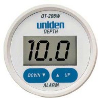
Before our July cruise, I installed the Hawkeye Depth Finder Model #D10D because my previous low-dollar depth finder (Uniden QT 206W) had failed. I’ve had a good opportunity now to compare the performance of both, and can definitely recommend the Hawkeye over the Uniden.
It seems that it is possible to pay up to $500 for a large format “sailboat” depth finder that mounts on the bulkhead. However, the availability of high-dollar stand-alone units is dropping off due to the popularity of consolidated multifunction displays for gps/chart plotter/depth finder/radar displays. And as I’ve looked at the market recently, I’ve noticed what seems to be greater selection among models and makers in the budget depth finder realm. I think makers of marine gear are understanding that the market for high-dollar gear has out priced the budget boaters, and they are now offering more products in the $100-$150 range, which is where I live as well. Don’t mistake this as altruistic behavior on the part of marine gear makers – I’m sure they are more motivated to not leave money on the table by ignoring this large group of boaters.
Regardless, the Uniden model represented a poor value with respect to construction and performance. I had this unit installed on my boat for about four years. After the first year, the display began to suffer from UV and weather-related damage, although it still functioned. The plastic display became frosty, the printed controls lost their readability, having faded in the sun. Finally, the display window cracked, which allowed moisture to enter the unit and make it unserviceable.
Performance-wise, it was inconsistent at best, but I must say that whenever I absolutely needed to know the depth when approaching shoal waters, it gave me the right information. This may in part be due to my choice of installation. I installed the transducer inside the hull without drilling a hole, and I didn’t glue it to the hull with epoxy – rather, I bedded it in a blob of silicone. I am confident this degraded its performance to some degree. It would never give much in formation in waters deeper than 50 feet, and often in choppy conditions it would return error readings, I assume due to the amount of air passing underneath its location just behind the vee-berth, or the inability of the processor to keep up with excessive motion as found in choppy conditions. When that area was ventilated by air bubbles, I feel sure the device had a more difficult time determining depth. Additionally, it featured a gain, or sensitivity adjustment on the back side, which was extraordinarily touchy.
By comparison, the Hawkeye, while still mostly plastic, features a glass screen. While vulnerable to impact damage, it is nearly impervious to effects of UV radiation, which means that the screen will always be readable. Additionally, it comes with a protective cover which will shield the unit from the sun during the many days and weeks when the typical boat is not in use. I did not install the new transducer that was included in the purchase. Instead, I determine through reading the spec sheet, that both Uniden and Hawkeye used the same frequency and wattage transducer. Not installing a transducer spared me a lot of trouble and effort with the installation. I was also curious how the unit would perform with the old transducer.
So at about the same price point (approx. $100 for each) the Hawkeye is a much better value than the Uniden. I feel more confident with this unit on board than I have with any other brand during our ownership of Cay of Sea – and early on, we had a “legacy” Datamarine large-format (read expensive) depth gauge.

Thursday, March 12, 2015
Chartplotter Support
Aboard s/v Suppose, Walt has constructed a very clever swinging mount for his chart plotter:
As we upgrade and outfit SV Suppose for cruising, we have tried to keep things as simple and bulletproof as possible. In particular, we want to minimize the number of things that, if broken, would keep us from departing from one anchorage and moving on to the next one. So, we have given a lot of thought to the electronics, weighing functionality against complexity and reliability. In the end, we decided on the Garmin VHF100 radio, GPS820 chartplotter, and AIS600 transceiver. By buying all Garmin products, it was "relatively" easy to interconnect them so that we can see AIS targets on the chartplotter and provide gps data to the VHF radio so that it can transmit a distress call with our location at the press of a button. We don't have radar now but the GPS820 can support it if we decide to add it later. So far, we couldn't be happier with this combination.
As with every other addition or modification to SV Suppose, the challenge was finding the space for the new electronics.
The VHF radio was the easiest and first component to install. I simply replaced the old one which had been mounted against the cabin top, just inside the companionway on the starboard side. Mounted there, it is out of the weather and can be seen, operated and heard from the cabin, companionway steps, and the cockpit.
This is the chartplotter on the mahogany support that I built for it. Here it is in its "stowed" position where it is not in the way for normal activity in the galley.
The AIS transceiver, mounted below the chartplotter, is just visible in this picture.
We don't have a separate navigation station in SV Suppose. Instead, we use the removable counter-top that covers the stove when it is not in use. For operation from this "navigation station," the chartplotter rotates out approximately 30 degrees. The chartplotter support is mounted on an 8 inch, brass piano hinge attached to the side of the companionway frame. To get the support to rotate in a horizontal plane, I placed a wedge under the hinge and against the companionway. The 8 inch vertical portion of the support and the diagonal brace underneath provide a very solid and sturdy base.
The chartplotter and its support will rotate a full 180 degrees where it faces into the cockpit. The base under the chartplotter is shaped so that it rests against the vertical frame of the companionway and overlaps the threshold. This provides extra support in case we should fall against it. It is held in this position by a nylon "bump" on the bottom of the base that slides over the companionway threshold which is a little higher on the inside edge.
The chartplotter support is held in the stowed and 30 degree positions by this block that is mounted on the inside of the companionway bulkhead.
A toggle that rotates against the vertical portion of the support locks into two positions against the block. The dowel stub in the top of the toggle makes it easier to rotate the toggle with a fingertip.
And here is the base rotated to the 180 degree position. In this picture, it is easier to see how the shape of the base allows it to swing around the side of the companionway and overlap the threshold.


Tuesday, October 21, 2014
Low-Buck Projectapalooza
Over at Dock 6, Brian has experienced those two best days of boat ownership:
- The day he sold his boat
- The day he bought his new boat
"Yes, I'm workin' all the time..."
-Rush
The stages of New/Old Boat ownership:
Stage 1. Admiration stage- admire how much roomier (or prettier or shinier or faster or just plain better your New/Old Boat is than your Old/Old Boat.)
Stage 2. Installation stage- Start installing stuff. Begins approximately 7 minutes after the onset of Stage 1.Stage 2 never, ever stops.
If you have bought the right boat, the first stage never stops, either.
Having lived with and aboard NextBoat for almost 3 months, much Low-Buckness, and some Mid-Buckness, has ensued.
For those of you still following along, (thanks!) you know the story. For those who just stumbled into this meandering morass of a blog, here’s the short version:We owned a boat, wanted a slightly bigger boat, found a bigger boat, bought a bigger boat, sold the slightly smaller boat…
Now we are pouring money and time and effort into the slightly bigger boat.
And enjoying every minute of it.
The upside of NextBoat is that she had been well maintained by two previous owners. The downside is that there were few upgrades, and some gear that we consider necessities was missing entirely. Like, oh….
A compass.
Didn’t have one.
Apparently, never had one since new- the binnacle was as smooth and unblemished as a baby’s transom.
We'll come back to that later.
So, after peering into the purse and seeing the present paucity of pennies, (prolonging our perpetual pondering of whether we are presently poverty stricken or penurious,) providence presently allowed us to press the button on a plenitude of purchases, provided by the profits of this profligate’s penmanship.
In other words, I got paid for some scribbles. Cool.
So, with cash in hand, we got all Bugs Bunny and Road Runner on the boat.(Okay, come on, I can’t be the only one who remembers the theme to the “Bugs Bunny and Road Runner Hour”? Come on, sing it with me, “….On with the show, this is it…”)
er...
*turns the Obscure Weirdness dial down to 7*
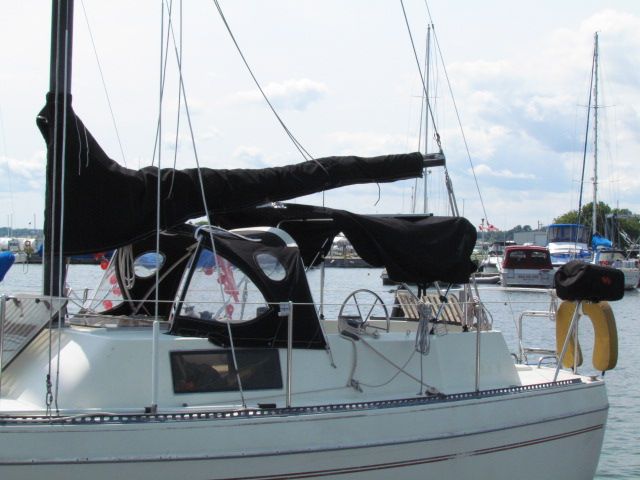
A flurry of mouseclicks and credit card approvals and straight-up hand-to- hand cash transfers later, we had a whole bunch of new stuff to stuff aboard our new ride.SWMBO is a ginger, and with a redhead’s propensity to burst into flames upon exposure to sunlight, she immediately noted that NextBoat lacked cockpit canvas of any sort. A shadeless boat with a redhead aboard is an unhappy boat for all aboard. Luckily, a beaten and battered and unused-by-the-previous-owners dodger was included in the purchase.
It needed help.
Canadian Canvas Works underpromised and overdelivered, restitching the entire top in less than 48 hours.
The skipper of Cyclone sold us a languishing bimini from his currently-for-sale S2 8.0A, and with a little cutting and sweating we soon had a comfortable cockpit.
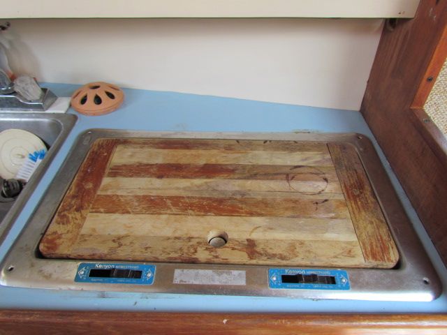
The stove that came with the boat had to go. Kenyon Homestrand pressurized alcohol stoves may have worked just fine when new, but 30+ years later….
… not so much.
The scary quotient, however, had increased considerably.
After following the less-than-simple lighting instructions, ( Pump tank of flammable fuel, tunr burner valve to introduce flammmable fuel to burner, close burner valve, light flammable fuel, let it burn out, then reopen valve and relight ) we inevitably faced a *WOOF* of ignition, resulting in burners with flames that had only one setting- Total Conflagration.
Seriously, the few attempts at using this DeathBlaster stove to create Two Burner Tastiness resulted in singed entrees trailing the faint odor of burnt eyebrows.
A quick click to Binnacle.com got us a great deal on a Cookmate non-pressurized alcohol stove. Under $250, including shipping.
Installation took less than a half hour, and the result is incredibly satisfactory.
Great temperature control, easy to light, and the burner capacity is measured in weeks, not hours. 6 weeks of regular use have borne out the value of this investment.
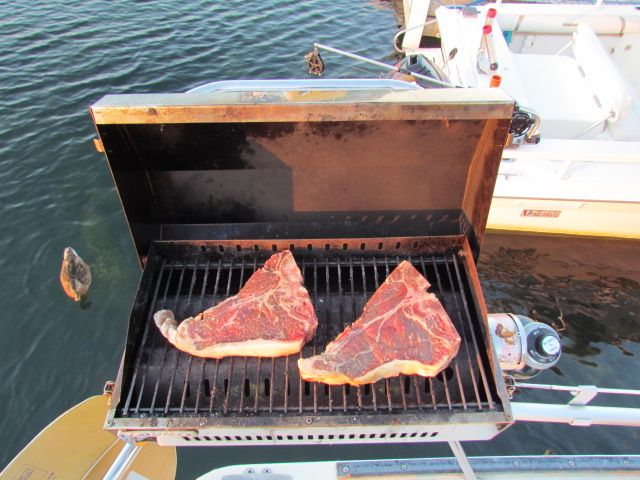
Further, we have upped the culinary ante by permanently installing the Kuuma Stow-n Go propane grille we bought during our first season aboard Whiskeyjack, but rarely used.
We have used this grille more this season than in the past 6 seasons combined.
Which means we are using more propane.
Which presents another challenge: Storage.
The one drawback to this center cockpit layout is that it eliminates all cockpit storage- no lockers, or lazarettes or cubbies on deck at all. I had no desire to store 1 lb. propane cylinders in the cabin, so a solution was required.
A quick trip to Home Hardware netted 2 feet of 6" PVC pipe, an end cap, a cleanout, and a couple of hose clamps. Less than $25 later, we were able to store 3 propane bottles on deck safely.
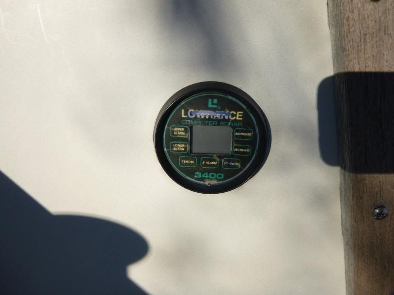
So, back to that no-compass thing: The existing cockpit instrumentation on NextBoat consisted of an inoperable Lowrance depth gauge.
That’s it.
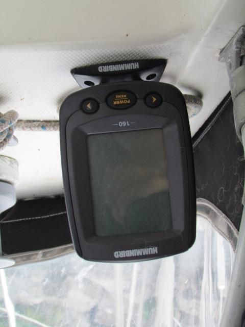
A quick trip to Dovercraft Marine netted us a Humminbird 160 fishfinder for $80. Some headscratching on where to locate the transducer and how to route the cables and roughly an hour or so of sweating and drilling and and wiring later, we not only had depth display, but water temperature as well.
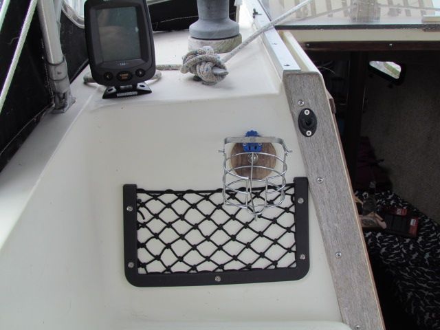
Back to that absence- of -cockpit- storage issue:
I picked up a couple of these mesh map pockets a half decade ago, and finally got around to using one! Very handy for books, sunscreen, sunglasses, all the stuff that would otherwise end up in the way.
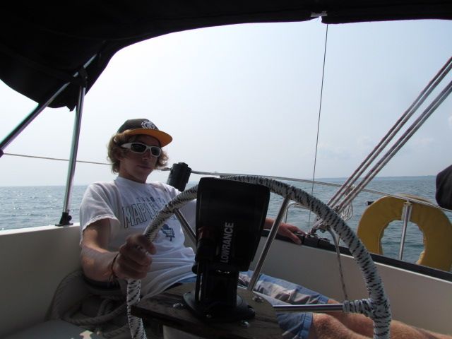
With depth out of the way, time to deal with the compass issue. I opted to go with a small handheld compass as a backup to a small Lowrance chartplotter at the helm, from Radioworld.
I LOVE these things. Lowrance "Gold" plotters include a 2 gig Navionics chart card, and the plotter we had on Whiskeyjack never let us down. The seated helm position on NextBoat makes the 4"ish screen size practical, and, though small, the screen is easy to read, the controls are intuitive and the menus easy to understand. The included mount swivels and tilts, making it viewable from anywhere in the cockpit....
...even if you are a slacker teenager, as Jordan demonstrates:
$250 well spent.
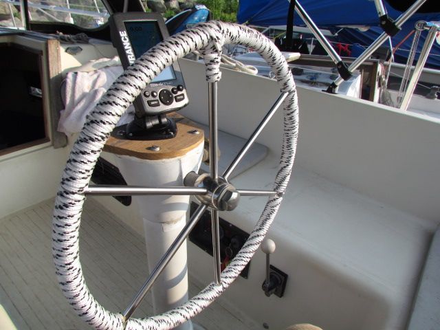
$3 worth of 1/4" line and an hour or so of time dressed up the wheel...
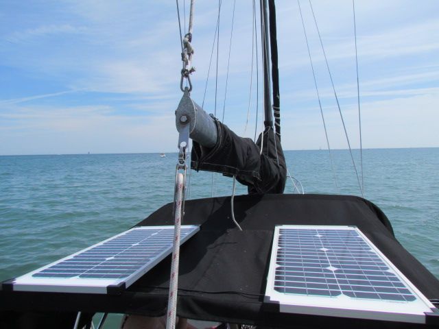
All of this new electrical gear requires improved electrical charging management- Two $99 40 watt solar panel/ 7 amp charge controller kits from Canadian Tire were installed to charge the battery bank. When docked, or flat water motoring, the panels live on the bimini-
When the wind picks up, they migrate to the aft deck. An upcoming project is to sew pockets into the bimini to secure these lightweight panels up there full time.
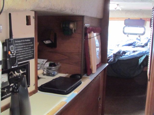
Down below, hammocks were hung and bungies were strung and non-skid mats were laid to keep everything that has a place, in it's place.
The settee-berth did not have a table, although there was one installed at some point in the past:
A while back some of the stuff that James was clearing out of his boat shed ended up in my boat shed. Among the assortment of stuff was a table base and post. a little plywood and edgebanding later, we now have a salon table:
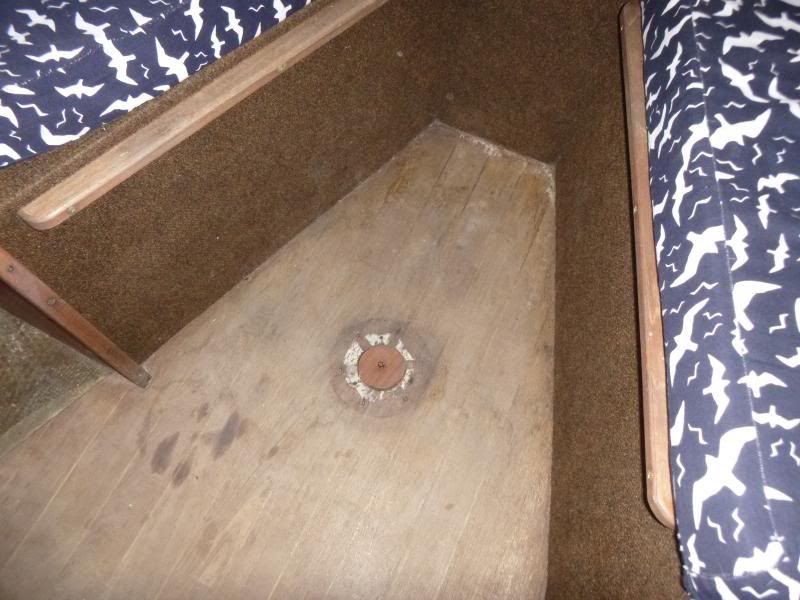
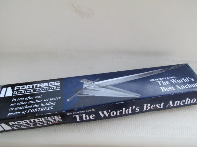
We managed to bend the shank on the anchor that came with NextBoat, and decided this was an opportunity to reduce weight on the bow and make anchoring a less strenuous task for the crew on the foredeck, by replacing the current steel anchor with an aluminum Fortress anchor....
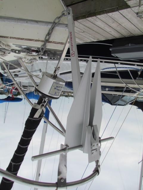
...which requires assembly.
slightly larger flukes, slightly longer shank, half the weight of the previous anchor should make anchor launching and retrieving easier.
We'll let you know how it goes.
Last but not least, a quick little project with a big "why didn't they do this from the factory?" factor:
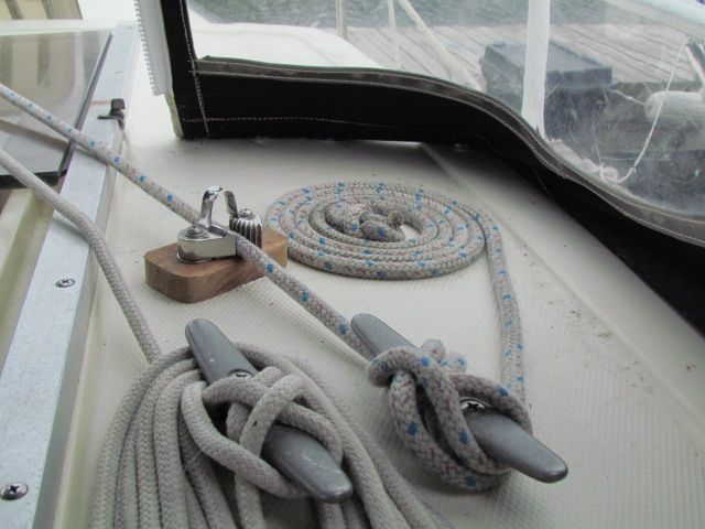
There are no clutches on the cabin top, and the only cleats are horn cleats...
which leave much to be desired when it comes to tying off halyards. You get a couple of wraps on the winch to get a full pull on the mainsail halyard, only to lose tension when you try to secure the halyard around the cleat, leaving you with a baggy sail.
We installed a cam cleat ahead of the horn cleat. No more baggy sails for us!
We also ran the mainsail reefing line to the coachroof, enabling us to reef the main without having to leave the cockpit.
Finally, we made life easier for the mutts. We carpeted the companionway ladder, to make it easier for them to climb/descend.
Ellie demonstrates that she now has ample room to run around.
Lots more projects ahead, lots more work to do, but, she's getting there.
She is becoming a home.
"Talk the Dock!"


Tuesday, October 14, 2014
Navigation Station Redesign
John continues spiffing up his Catalina 30, s/v Dulcinea. Today, his project is a complete redesign and rebuild of the nav station. This project may be pushing the limits of what a "small" boat project is, but it is so chock full of goodies that I knew you'd want to see it!
There were a few things I didn't like about the Navigation Station.. First, the angled desktop kept everything on it sliding down, and sometimes to the floor.
there was also no place to mount the VHF radio except to the aft side, vertically.
the VHF radio mounted on the aft side of the station... this pic is taken looking down
Also, I want to eventually move all of the electrical panels to the Navigation Station, a more logical and safer location in my opinion, than the current location on the aft bulk head, where the backs of the panels are exposed to the Lazerette, albeit under the line locker, but I think it is possible that things could shift in there and come in contact with the panels, possibly shorting things out, or worse. currently there is no place to put the panels at the nav station.
Not a great place for electrical panels... the back side is open to the Lazerette, and is near the sinks.... oh, and see the round instruments on the far right? that is the engine hours and fuel tank indicators.... REALLY inconvenient, have to bend over the stove to read them! What genius thought that would be a good place?
Sooooooo, A redesign of the station is in order. First step. some boat Yoga to yank it out!
This is the downward-jam-yourself-into-small-spaces Boat Yoga position
My Brother-in-law removes the retaining board.
Halfway out!
Gone! Yuk! 37 years of dirt and grime under there!
When I dismantled the station, I discovered that the shelf that separates the top and bottom compartments was made out of Teak ply! Bonus! I will need this later to extend the vertical "Ears" to the bottom the deck! So I replaced this with a piece of Exterior Plywood.
Next, in my original design, I need to cut a Isosceles triangle out of the sides, but they had to be identical on each side... hmmm... ah! I stacked them (flush in the front), and then clamped them together. I will cut both sides at the same time! (Note I say the ORIGINAL design.... keep this in mind....)
Cut along the line with my trusty Jig saw....
here is a little trick when cutting out pieces like this... cut the first side, then put a clamp on top of that first cut, then cut out the second side.... this keeps the piece from flopping and binding the blade, not to mention from dropping to the floor after cutting the second side.
I was so happy with the way it turned out that rather than taking it back to the boat for a dry fit, I just sanded, patched, reassembled and refinished it! This was gonna be GREAT! I didn't even have to modify the desk top.... I thought I was going to have to cut some of it off! (ominous music plays here)
Doesn't this look great? Gosh I'm good!
So, being the happy camper I was, I put 6 coats of Varnish on the whole thing!
By the way, I agree with my friend Robert Salnick at WindBorne in Puget Sound on the subject of Painter's Points.... Get 'em and use 'em!
Then it was time to install it in the boat!! THIS is when I found out the FLAW in my design.... you see, I didn't account for the shelf on the right side of the Nav station.... see the fiddle on the desktop below? it is supposed to be an inch or so to the right, overhanging the edge of the nav station.....
Whoops! The desktop is supposed to be an inch further to the right.... the shelf blocks it!
see how the left side has a Big over hang and the right doesn't? This isn't gonna work....
Soooooo..... time for a redesign of the redesign. The first step was to remove the "ears" that weren't wide enough....
removing the ears using my Dremel Multi-tool
Then I created some cardboard templates that went from the bottom of the deck to the top of the nav station... Notice there is a channel that I had to work around on the bottom of the deck. Also notice these are MUCH wider than the original "ears"
the ear is cut off.... now for the other side....
Then I added a shelf to separate it into two sections, and to add some stability. I mounted blocks so I could attach the face plate. And what is that thing in the middle? Stay tuned!
The template laid out... remember the teak ply shelf I replaced? this is where I needed it!
Now to address that weird black spray painted thing in the middle.... Notice the location, just under the stereo. You see, my stereo connects via blue-tooth to my phone or Ipod, but I needed a place to put these when underway. So I made this little cubby hole. Put a little bit of anti-slip material in the bottom and Voila! It also is a great place to put pencils and pens too!
Building the top part of the Nav station. the area above the shelf is for the radios..
Now to take the newly fabricated top to the boat! This time I measured Many times, so all pretty much fit like a glove.
The Cubby hole for my Ipod and Phone (Ipod is in the cubby right now)
I needed a way to connect the upper and lower parts of the nav station, and not wanting to waste anything, I figured this was a good place to use the old ears!
YEA! Now the desk top fits like it is supposed to! WOO HOO..... no, wait a minute... Uh oh....
Darn it! I guess I am going to somehow modify the desktop..... It sticks out WAY too far.... More measurements, and take the desktop back home...
Looks great from the front!
Now I wanted to cut this desk top down, but I did NOT want to remove the fiddle rail, and I didn't want to chip the Formica top. So, I used some tricks I learned when renovating houses I have owned in the past...
First step is to put down painters tape so the cut line is in the middle of the tape.
Now, Normally you want to cut the counter top with the Formica side down, to virtually eliminate the chipping that will happen when it is cut. I could not do that in this case because of the Fiddle rails, so I had to cut it the other way..... MAKE SURE you use a Plywood blade on your saw (many 32 teeth per inch or better) AND have the blade just BARELY CLEAR the top. Then go SLOWLY.
Blade JUST clears the counter top
the Cut is complete
Since the blade didn't cut through the Fiddle rails, I finished it off with a hand saw...
Then it was time to hold my breath and remove the tape, to see how badly it chipped......
And, amazingly, not one single chip! Nice!
Finally I had to ease off the top corners so the desktop will open without binding. I used my trusty belt-sander for this. It made quick work of it!
and now I have a finished desk top..... back to the boat for the third time!!!!! while I was doing all this, I also made a door for the top part of the Nav Station, so now it was time to install them both!
The inside of the station, under the desk top
And so this Project draws to a close.... FINALLY! I have to find a way to make these posts a bit shorter, but this project was a big one.... I will cover the installation of the Radios and the associated wiring in a later post... this one has been long enough! But I am really happy with the results!
LOTS of storage in here... for now.
Coming up.... Installing the radios (it will be a shorter post! LOL)
What'cha think?
Till next time!
JEM


Subscribe to:
Posts (Atom)


