Showing posts with label corrosion. Show all posts

Tuesday, July 12, 2016

Corrosion, Corrosion

This post originally appeared on Windborne in Puget Sound

For a boat on salt water, corrosion is an omnipresent demon.


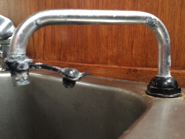
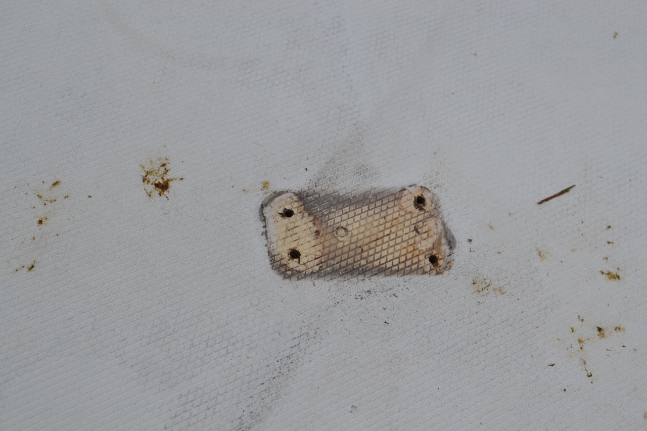
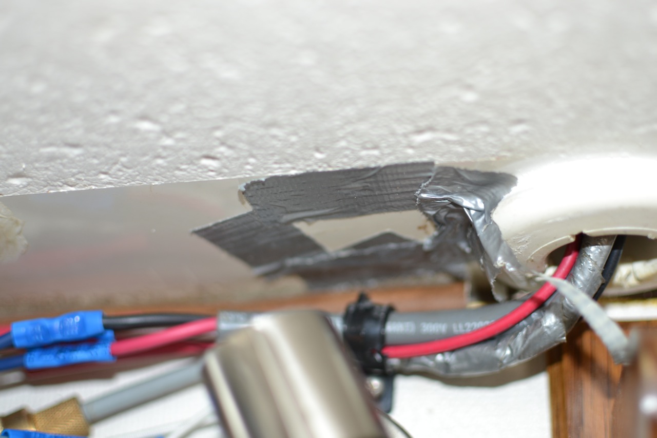
Even inside.  This is the spout on our galley sink which is piped to a saltwater foot pump. And to the cooling water discharge from our 12V refrigeration system, meaning that it has saltwater flowing out of it whenever the refrigeration compressor is running, as a telltail. Look closely at the inside of the right-hand bend... yup, the aluminum has corroded thru. I don't understand this... aluminum is supposed to be reasonably proof against saltwater.  The pipe is clamped to the sink in a plastic fixture, and is connected below the sink via vinyl tubing...  ruling out galvanic corrosion.  The entire refrigeration system is 12V, so stray 110V current cannot be an issue.  The compressor is powered by an external motor thru a V-belt. 

But.

The motor and compressor are mounted on the same metal plate, and there are some pressure switches to control the motor mounted on the compressor.

Is that enough to cause stray current corrosion, tho there is no direct connection between the refrigeration unit and the aluminum tubing except via the saltwater itself?

Or is the corrosion simply the result of flowing saltwater washing away the protective oxide layer on the inside of the aluminum tubing?  I am very interested in what the net.wisdom has to say about this...

Regardless, this is the second spout that I have installed there, and they have gotten ridiculously expensive.  I am not planning to buy a third one.

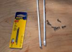
Two pieces of 7/16" stainless tubing
Instead, I bought some thin-gauge 316 stainless tubing from Online Metals.  Now, if you've ever attempted to bend tubing, and especially thin-gauge tubing, you know that it requires special tooling to prevent kinking.  The tooling constrains the tube so that it can't collapse and kink while it is being distorted.  I looked up what a tubing bender for 7/16" tubing costs on the Interwebs, and Oh. My. Gosh.

OK, a Plan B is needed.

It is also possible to prevent collapse/kinking if the tubing is filled solidly with something incompressible.  Apparently some people have used ice (fill with water; freeze), but I was concerned that I'd never get the tubing bent before the ice started to melt.  This is where Wood's metal comes in.

This is Wood's metal - it is a eutectic alloy of 50% bismuth, 26.7% lead, 13.3% tin, and 10% cadmium by weight.  It melts at 158°F
I just happened to have some. 

Wood's metal foundry
For a foundry, I purpose-bought a can of tomato paste (69¢), and froze the tomato paste, retaining the can - just the right size.  I put it in a pan with some water and brought the water to a boil - 212°F, or about 50° of superheat.  I then poured the molten metal into the tubing (I had previously blocked one end of the tubing by pushing it into a wine cork - we seem to have plenty of these).  I then immediately plunged the filled tubing into a container of cold water - I had read that quenching creates a fine crystal structure in the Wood's metal, making it more ductile (read: easier to bend).

OK, now to bend.  I created a bending jig and lag-bolted it to a 4x4 in our shed:

Homemade bending jig
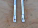
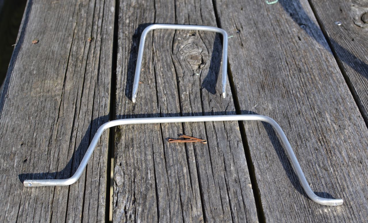
Yup, it bent just fine - no kinking, no collapse.

Recovering the Wood's metal
All that remained was to reheat the bent tubing in another boiling water bath to remelt the Wood's metal and pour it out.

And since our galley sink has two of these spouts (one for salt water and one for fresh water, foot-pumped from the tanks), I made another spout.  Gotta be symmetrical, don't you know.


Done
(Clever camera angle conceals dirty dishes in the sink)
A little boat yoga, and the galley sink looks better than it ever has!


Tuesday, May 19, 2015

Steaming Lamp/Deck Lamp Guard

Over aboard s/v Cay of Sea, Rick avoids paying the marine tax by fabricating his own guard for his steaming lamp:
Okay, I’ll admit that I don’t know exactly what to call this thing, but I know what I want it to do – what I hope it will do, if it is robust enough to do so. First, some background:

Two years ago my deck lamp was knocked out of the fixture, including the lens (I think), by an errant halyard slap in high winds. Well, that wouldn’t be too bad, except that I had just replaced it. It’s one of those two-pronged halogen 20 watt lamps, and they are sort of pricey. Not only that, but I hate going up the mast. Now I’d have to do it again! There has to be a better system. I imagined at the point, that some sort of cage of rods would be an adequate protection against another halyard slap. I’ve seen them on other boats, but I’ve never seen one advertised for sale, so I have no idea of availability or price. But how hard can it be to make something like that? While the mast is still horizontal and I have time before launch, I thought I would give it a try. I should be able to come up with something.

I went to the hardware store today to look for materials, and came home with 36″ of 1/8″ aluminum rod, eight stainless #6 screws, and a drill bit and tap for #6 screws.

Back in the shop I cut the rod in half and flattened the ends of the two pieces with a 3-pound maul against my closed vice, then drilled holes in the ends for the screws. I used a mill file to clean up the sharp edges.


Back at the boat, I estimated the lengths, attachments points, and the approximate locations of the bends. Without a vice on site, I found convenient places to capture one end of the rod while bending the appropriate place against a leverage point. This is what I came up with:

I managed to get one leg of the smaller piece longer than the other.  Doesn't really make a difference.  It attached to the mast without complication.
I managed to get one leg of the smaller piece longer than the other. Doesn’t really make a difference. It attached to the mast without complication, but it does bother me that the legs are not exactly the same length. . . 

I located the larger piece on the mast first and marked the attachment points. Using a steel punch, I made a small divot point in the mast at each screw hole location to get a clean start with the drill bit. Carefully locating the drill bit, I used significant pressure and slow speed to start the hole (the mast is a curved section, remember? Hard to drill a hole in something like that without having the bit walk all over the place). Each hole started and finished cleanly. I cut threads into each hole with the tap, then ran a screw into it to ensure clean threads. If you never tapped a hole, it’s an interesting process. Everything is extremely low tech, except for the tap itself – which is hardened steel, tapered at the point, with the cutting threads beginning immediately. I use a small adjustable wrench to turn the tap a quarter turn at a time as I guide it into the hole as perfectly perpendicular as possible. It’s helpful to back the tap out a quarter turn after every complete turn or so, to clean the metal debris from the cutting threads.

I marked, drilled, and tapped for the second (port-starboard) piece next, then mounted both pieces with screws well bedded in TefGel. TefGel is a non-conductive corrosion inhibitor, and it allows me to use stainless fasteners into an aluminum mast without threat of galvanic corrosion. Every place I’ve used it on the mast has been completely corrosion-free since I refit the mast eight years ago.

In case you’re wondering, sheet metal screws, or self-tapping screws are an inappropriate fastener for this application. In fact, anything screwed into the mast should be done with machine screws. They have much finer thread than self-tapping screws, and hold much more securely. I like what Don Casey says about sheet metal screws in a mast: “I’ve never seen a sheet metal mast . . . ”

Point taken.

After fitting both pieces, I linked them with a zip tie, reasoning that having them linked together would give them a bit more rigidity (4 attachment points, vs 2).

Here’s the finished product:

DSC_4333
DSC_4334
DSC_4335

Nice rounded features should allow halyards to slide right off and past the light. Cost? About $10, including the drill bit/tap set. We’ll see if it does what I hope it will. Although the rod is quite bend-resistant, the fasteners could be the weak point. As long as they don’t get wobbly, I think it will be fine. They are torqued as tight a I dare and seem quite sturdy, although it may be smart to install lock washers under the fastener heads. Any opinions out there about this?

Thursday, October 2, 2014

New Deck-Mounted blocks Installed

Rick renews the blocks which the running rigging blocks on s/v Cay of Sea. This is a good example of how to do deck mountings that will not leak into the core:
Another multi-step projected mostly completed today.  Yesterday I removed the old blocks from their long-held locations on the coach roof.  These poor blocks were in sad shape.  One had lost its cage, another had lost half of its sheave.  3 out of 4 of them still actually turned and conveyed the line along its way, but not very well.  And none of them were installed correctly – by this, I mean they were fastened by a variety of means, sealed with silicone, or fastened with stainless screws into the aluminum mast step plate.  One of the blocks was actually fastened with .5″ self-tapping screws into the top skin and partially into the core.  For all of that, none of the core was wet!  Amazing!  Here are some of those sad images.  I’m embarrassed to say that I haven’t addressed it until now.
Here's a photo of the motley crew.  Sad bunch, these guys were.
Here’s a photo of the motley crew. Sad bunch, these guys were.  Not one piece of matching hardware.

This guy firmly was secured  with wood screws.
This guy firmly was secured with wood screws.

Right into the core.

DSC_3263
I didn't even really try to unscrew these fasteners.
I didn’t even really try to unscrew these fasteners.

One quick test with the screw driver told me they would never budge again.  I cut them off with a Dremel.
One quick test with the screw driver told me they would never budge again. I cut them off with a Dremel.

Bolt stubs cut off.  See the corrosion where the stainless contacted aluminum?
Bolt stubs cut off. See the corrosion where the stainless contacted aluminum?

After removal, I filled the old holes with thickened epoxy, using a resin syringe to fill from the bottom. I taped up the underside with duct tape to keep it from running out, and that was the end of work yesterday, as I had to wait for the resin to cure.
Can't really see it, but there is duct tape up against the coachroof (beyond the liner), keeping the resin in place.
Can’t really see it, but there is duct tape up against the coachroof (beyond the liner), keeping the resin in place.

Taped up through-holes.

Holes slightly overfilled.

DSC_3277
I began today by sanding the over-fills flat, then examining the halyards for placement of the blocks.  I finally ended up mounting the mast turning blocks farther outboard in order to clear obstructions. Mounting them back onto the mast step plate was a non-starter.  The halyards led that far from the mast looks a little strange to my eye at this point, but it is completely functional, will actually reduce halyard slap.
Overfill sanded flat.

DSC_3280 DSC_3281
After positioning the new blocks and fairing the alignment, I drilled the new mounting holes.  I first drilled a small-diameter test hole and went below to see where it came out.  There are lovely teak decorative strips installed athwart across the overhead.  I didn’t want to ruin any of those.  After adjusting two of the block locations, I completed drilling the holes oversize, then filled them again with thickened epoxy.
It was gratifying to see dry wood dust come up with the drill bit.

I drilled 7/8" access holes where each fastener hole came through.  I had considered obtaining white plastic cover buttons for these holes, but there are too many of them.  I will cover them with either a teak plate from scrap, or a cover plate from some kind of white plastic.  I'm leaning toward the teak.
I drilled 7/8″ access holes where each fastener hole came through. I had considered obtaining white plastic cover buttons for these holes, but there are too many of them. I will cover them with either a teak plate (all four with one cover plate) from scrap, or a cover plate from some kind of white plastic. I’m leaning toward the teak.

Here's a really ugly set of holes.  Old and new combined.  One rectangular teak plate will cover all of that nicely.
Here’s a really ugly set of holes. Old and new combined. One rectangular teak plate will cover all of that nicely.

After the epoxy cured, I redrilled the mounting holes the correct size for the fasteners, then beveled the top of each hole with a countersink bit.  This allows a “pool” of sealant to completely surround the fastener, providing a more sure water barrier, especially when the butyl sealant is put under compression.
Epoxy potted holes redrilled, and countersunk.

This is the first project involving deck piercings for which I’ve used butyl tape as a sealant.  If the tape is as effective sealing out water as it was easy in application, I’m sold.  This is usually the part I hate most about a project.  Lifecaulk or any other sealant is so completely out of control, such a mess to apply and clean up, no matter how careful I am.  Butyl was a piece of cake.  It’s sticky, pliable, tacky, moldable, squishable, but not messy.  Apparently, it lasts nearly forever.  What’s not to like?
Here's the butyl tape, rolled and blobbed around the fasteners and edge of the block.
Here’s the butyl tape, rolled and blobbed around the fasteners and edge of the block.

This is (was) a 30' roll, and inch wide, 1/8" thick.  I bought it at the hardware store for $10.  This stuff is supposed to allow for uninstallation too.  It stays pliable for decades.
This is (was) a 30′ roll, an inch wide, 1/8″ thick. I bought it at the hardware store for $10. This stuff is supposed to allow for uninstallation too. It stays pliable for decades.

And the moment we've been waiting for:  installed, lines in place, looking good.  This only took two days of work for four small deck-mounted blocks.
And the moment we’ve been waiting for: installed, lines in place, looking good. This only took two days of work to install four small deck-mounted blocks.

DSC_3292
This project will really be done when I’ve fabricated and installed the cover plates.

Thursday, December 19, 2013

Electrical system upgrade

Please welcome new contributors TC & Kelly aboard their Dragonfly 1000 trimaran s/v Wind Strider!  For their first contribution to Small Boat Projects, TC gives us a detailed description of his upgrade of the Dragonfly's electrical system. 

Most interesting to your correspondent is the use of LiFePO4 batteries - this is the first time these have appeared on Small Boat Projects.  I think we are seeing the future here. 
The biggest project during the winter 2011/spring 2012, and therefore subject to its own entry, was the electrical system upgrade.  As indicated by overnight anchorages in 2011, one of the two Optima Yellow Top house batteries had failed.  Further, the two, at least 10yr old, 60watt solar panels weren't doing anything.

With any change, one must ask to what end - what is the change to achieve?  The goal for the electrical system upgrades was to get at least 4 days on the hook without needing to recharge the batteries via engine or shore power.  Why 4 days?  4 days are probably how long Strider's fresh water supply will hold out!

Major Component Overview:

4 CALB 180Ah LiFePO4 Batteries with mini BMS
6 Aurinco solar panels:  2x Compact 100; 2x Bluewater 25; 2x Compact 25
2 Genasun GV-10 MPPT controllers
LED Lighting Throughout
MasterVolt ChargeMaster 12-25-3, MasterVolt MasterViewEasyMkII, MasterVolt MasterShunt, MasterVolt MasterDistro 500, MasterVolt MasterBus USB

What is the consumption?

To design an electrical system properly, one must first know the consumption, or what one uses. Every electrical item aboard must be taken into account:  Refrigerator, lights, radio, pumps (anchor wash down, bilge, galley, shower and head faucets), navigation instruments, hair dryer, fans, stove, windlasses, bow thruster.  Everything.  When Strider's systems were examined, stem to stern, I erred on the side of caution and rounded everything up, overestimating the consumption:  Summer worst case of 40Ah per day.  Winter, using the furnace and probably the stove more, would increase consumption. 

Second, one has to know how long they want to go between charging.  Since 4 days between charging was the goal, 40Ah x 4 days = 160Ah, the working number.  Batteries able to handle 160Ah loss need to be purchased.

LiFePO4

My mentor Steve, of the Dragonfly 1000 Flexible Flyer, turned me on to LiFePO4 batteries.   'Standard' batteries, gel, AGM, wet and 6volt deep cycle golf cart, had been looked into.  All had several drawbacks, weight and discharge capability were foremost.  'Standard' batteries are able to discharge a maximum of 50% without damage for a maximum of 500 cycles.  Going by the goal of 4 days on the hook and 160Ah consumed, batteries of at least 320Ah were required.

Looking at the 6volt batteries available, two 370Ah would do the trick.  However, while the could fit in the engine bay, they weigh 113lbs and cost $420 each!  Alternately, assuming the solar panels could keep up with consumption, the next size down 6volt is 215Ah (107Ah, not 160Ah available), weighs 63.5lbs and costs $238.  A little more reasonable, but still heavy.

Gels fitting into the original space under the step are the group 31s.  Each has 97Ah, weighs 72lbs and costs $410.  Two would be required for just 97Ah usable.  To get to the goal's 160Ah, 4 group 31s would be required (3 would fit under the step) or move up to the 4D.  The 4D has 183Ah but weighs 130lbs and costs $645.  Once again, two would be required and they would have to be fitted into the engine bay.

Then Steve mentioned he was replacing his 6volt golf cart batteries with LiFePO4, a single set for both house and engine start.  There are several lithium ion technologies and manufactures, from very expensive, all included, plug and play MasterVolt all the way to less expensive more basic build your own with components.  LiFePO4 are stable and a great amount of power available vs cycles:  70% discharge 3000 times or 80% discharge 2000 times!  Then there is the size and weight:  Small and very light compared to 'standard' batteries.

CALB 180s were selected because they offered a bit more Ah vs size.  Though a 400Ah version were available, 4 would not fit into the space under the stair.  Further, with the solar panels selected (see below), I began to feel the 160Ah requirement was something to be flexible on.  Though rated at 180Ah, they can provide 200Ah (charged above the rated 3.4 volts each).  Their rated power (180Ah) available vs cycles:  126Ah @ 70% discharge or 144Ah @ 80% discharge, close to the 160Ah requirement.  At 11x7x2.8in and 12.5lbs each, they total 50lbs and fit under the stair!  With these, barring something catastrophic, Strider will never see another set of batteries.

BMS

A word about the Battery Management System.  There are BMSs available which will do everything, protect and keep the batteries balanced.  I purchased a 'mini-BMS' which has 5 components, 1 monitor/battery and an overall control board wired to a solid state relay controlling the shore power charger.  The BMS does no balancing, this must be done by hand (not difficult).  To date, this set up works fine by shunting power across a battery when it is full and prevents the shore power charger from over charging the batteries.  I'm not sure it is required for this set up, but it is an insurance policy.

Steve provided a simple circuit to tie the BMS into the refrigerator t-stat so should the BMS cut off the shore power charger, all will be reset when the refrigerator turns on.  Now, how to keep them charged?

Solar

Wind was briefly considered, but dismissed as not practical for a Dragonfly 1000.  The solar setup was based on information gleaned through the Cruisers and Sailing Forums.  In particular:  The rule of thumb for peak solar is 4hrs/day year around in the southern latitudes, 5hrs/day summer-time north and (inferred) 3hrs/day winter-time north.

Again, worst case is winter sunshine is 3hrs/day peak.  To keep up with 40Ah/day, with zero loss, the panels needed to provide 13Ah for each of the 3hrs.  13Ah is about 180watts of panels (13Ah x 14volts = 182watts), round up and call it 200watts.

However, this is under ideal conditions:  All the panels oriented in the same direction and constantly oriented to the sun.  Aboard Strider, there is always shading, from lines, from sails, from the nets.  For instance, if under sail and the starboard is in full sun, the port side is shaded by the sail.  Further, the panels need to mounted on flat surfaces of the boat and none of them are oriented to the sun.  So, while 200watts would suffice in ideal conditions, there are no ideal conditions aboard Strider.  What then is required?  300watts?  400?

Aurinco panels were desired because they had a good reputation.  They did not need blocking diodes to prevent electrical flow from a producing panel to a shaded panel.  They are thin and light with a non-skid surface.  And being somewhat flexible, they are able to bend to mount on the boat's surface.  Further, they are local (Anacortes, WA).

Aurinco's panel styles helped to decide what and where to be mounted.  Strider came with two, 10yr old, 60watt panels and they needed replacing.  Aurinco's 100watt panels were the same size!  So, two of those, one for each ama.  Their location however, is covered when the amas are folded.  When the amas are folded, locations left exposed included the tops of the akas and the aft end of the amas.  Conveniently, Aurinco has a 25watt panel that would fit on top of the aka and a second 25watt that would fit on the aft end of the ama.  With this set up, I'd have 100watts exposed folded (7Ah max ideal) and 300watts extended (21Ah max ideal).  Remember:  There is no ideal aboard Strider, but I thought all in all, 300watts could cover our consumption.

To date, I've been very happy with the panels.  One needed to be replaced as water intruded via the output wires and caused corrosion/delamination.  Aurinco was very accommodating.  For further discussion, there is a results section below.

Solar Panel Arrangement.
The large 100 watt panels on the ama are covered when Strider is folded.
The small panel on the ama sterns are 25 watt.
25 watt panels are on the aft akas.

MPPT

A controller is required to regulate the nominal 18-21volt solar panel output to something the batteries can handle.  The latest technology is Maximum Power Point Tracking (MPPT), a technology some claim to increase useful solar output 20-30%.  Practical experiments at Aurinco showed a more modest 10% increase.

The entire system was split into port and starboard, two systems of 150watts each, for redundancy.  A no bells or whistles MPPT by Genasun was selected for each side.  Genasun GV-10 can handle 10.5amps and claim a 98.3% efficiency with .9mA night time consumption.  Because CALB LiFePO4 batteries had been selected (see above), the GV-10s were programed for a 13.8volt charge to protect the batteries from a potential overcharge.  Later, I found out the GV-10 came with a 13.8volt float voltage, this alone woulda/coulda protected the batteries.

Why 13.8volt charge?  Though a Battery Management System was purchased with the batteries, I was unsure the BMS did anything except shunt power across a battery once it is charged and shut off a shore power charger to prevent an overcharge.  So, 13.8 is derived from the CALB charge chart showing each battery is charged to maximum capacity at 3.4volts.  3.4v/battery x 4 batteries = 13.6volts.  .05volts/battery is required to overcome internal resistance.  .05 x 4 = .2volts.  13.6 + .2 = 13.8volts.  Unknown to me, there was a conversation between my supplier and Genasun at my 'unusual' voltage request of 13.8.  According to Genasun, CALB normally requires 14.2volts.  Would this have changed anything?  Not likely, I wanted to protect the batteries...period.  For results, see below.


LED Lighting

LEDs were not a part of the original consumption calculation, the original halogen and incandescent were.  But opportunity presented itself and with the exception of 1 light in a small cupboard, all Strider's lighting was converted to LED, including the navigation lights.  As a result, Strider hardly uses any electricity for lighting.  Navigation lights are Dr LED via West Marine.  Internal lights are Phillips 12volt LED garden lights via Home Depot.  The galley overhead light was replaced with a red/white LED light fixture.  The white side of the light was wired to the stock overhead light above the cook top, increasing light in the galley.  The light in the head was replaced with the same fixture as the galley.  The goose neck map light behind the dashboard in the cockpit was replaced with a red/white light also.  Now, red light is available from the V-berth all the way to the companionway and into the cockpit making night egress easier without sacrificing night vision. 

I have no direct Strider data, but an efficiency example is:  Summer 2012, a buddy was having problems with his boat's electrical system and the masthead incandescent alone was using 16Ah per night.  An LED was loaned and the consumption went to near zero.  This same buddy said Strider's masthead light was very visible (rated at 2nm).


Monitoring

Strider came with only a single output, conventional battery charger and a rudimentary monitoring system (volts only).  Though there are less expensive components available, MasterVolt was selected because each component is compatible with all the others - they communicate and are programmable.

MasterVolt ChargeMaster 12-25-3.  Fully programmable.
MasterVolt MasterViewEasyMkII.  Monitors and allows some system programming.
MasterVolt MasterDistro 500 distributes the power to the boat systems and has 4 ports.  One is connected to the stock, 65-amp alternator, one to shore charger, one to port solar and one to starboard solar.  The type of fuses used in the shunt were readily available for the alternator and charger, but there were none small enough for the solar so I had to create my own.
MasterVolt MasterShunt measures and monitors flow in and out of the batteries.
MasterVolt MasterBus USB connects the system to a small notebook computer carried aboard and via the MasterVolt software, components can be programed.


Settings

The ChargeMaster is set at 14 volts (could not go lower) and floats at 14.  However, it is used only occasionally, mostly during the winter when shore power is connected and an electric heater is running on board.  To date, the batteries have had no problem with this setting.  When the batteries are down, the stock alternator outputs 45amps @ 14.2 but throttles back to 2amps @ 13.8 as the bank charges.  Originally, the GV-10s were set at 13.8 volts (turns out this is also their float voltage).  After a summer of use, the GV-10s were sent back to Genesun and reprogrammed to 14.2volts in an attempt to increase charge rate.  A neutral result (see below).


Results

So, after thousands of dollars and millions of lives, how well does this system work?  In a word:  Fantastic!  Spring, summer and fall, with the amas folded and only 100watts of solar panels showing, the refrigerator on, the batteries are kept charged to 100% during the day, even during overcast days.  Winter in this configuration, with thick overcast and rain, the 100watts solar cannot keep up with fridge.  So the fridge is shut if off and the batteries stay at 100%.

Once aboard, with amas out, there is excess power and a freezer was added.  Once the freezer was dialed in, Strider uses 12-15 Ah between sun charges, including using the diesel cook top and furnace in the morning.  Generally, Strider is fully charged around 11am.  If there was a water maker, Strider could be on the hook forever.

The worst consumption/charging experience was before the freezer had been dialed in (originally set too cold and running too much) and anchored in a bay surrounded by trees.  The panels received the morning sun around 8am but were shaded by 4pm.  Additionally, due to angles and shading, the panels were not getting much exposure at all.  Further, these days were hot, about 85 degrees interior temperature, so the freezer and fridge were working hard.  In these conditions, the system was loosing between 10 and 15Ah per day.  Still, after 4 days, Strider was only down about 45Ah.  Not bad!  Winter, the original worst case scenario, has not yet been fully tested.

Improvements?

What would improve the system?  Steve's Flexible Flyer has 320 watts solar, 240 Ah LiFePO4 batteries (different brand), super-insulated, water-cooled fridge, a water maker and has enough excess power to heat his hot water to 170 degrees via the inverter.  His panels are set up more optimally and Strider will never be able to match his output without the addition of an aft arch (dinghy davit/radar/panel structure) like Flexible Flyer.  Still, he has achieved up to 19amps output.  The best seen aboard Strider has been 7amps...not even 50% of the solar panel potential.  As mentioned the GV-10s were sent back for reprogramming from 13.8volts to 14.2volts.  I'd hoped this increased voltage would increase the amp flow, but it doesn't seem to have made a difference.  Next step is to move the 100watt panels to a better location, forward on the ama, just behind the hatch and less shaded by the nets.  The configuration is working great as is, improving output is just something nagging.

What else?  Perhaps add an inverter.  But at this point, everything aboard is 12v or hand crank (blender and coffee grinder), which is fine!  However, my wife goes without a hair drier (but it would be nice).  Doing the hot water system like Steve does would also be nice.  We've a 'bucket head' vacuum cleaner for in port, else a small broom and dust pan is used.  Another addition would be a watermaker.

But all the additions mentioned are improvements to creature comforts, not system improvements.

Conclusion

The goal was at least 4 days on the hook:  Achieved!  The worst case to date was in Tenedos Bay in BC's Desolation Sound.  Even in these conditions, 4 days was easily achieved and Strider probably could have gone 2 weeks.  Anchored in wide open False Creek (Vancouver), Strider was fully charged by 11AM.   So:  Was consumption grossly overestimated?  Perhaps, but the LEDs were not a part of the original calculation and made a huge consumption improvement.

Too much solar?  Even with the niggling improvement mentioned above, the solar panels have been great also.  Probably could have gone with 200watts in the normal spring/summer/fall conditions.  However, the excess does allow for expansion.  Winter conditions have yet to be tested.

The LiFePO4 batteries have been a huge success - maintenance and trouble free!  The other systems have also been maintenance and trouble free.

Best yet, Strider never hooks up to shore power in marinas spring/summer/fall nor ever run a generator.  Quiet!

Tuesday, June 25, 2013

Inflatable Rehabilitation

Unlike diamonds, inflatables are not forever. But with a little attention, they will last quite a while... Drew over at Sail Delmarva gives us some inflatable maintenance tips:
When I bought the boat I honestly did not expect the tender to survive more than a season or two. She was 10 years old and faded, and didn't hold air too well. It was just a matter of time. As it turns out, Hypalon is surprisingly durable stuff and 5 years later she's going strong... with some rehab.

This time it was a bit of peeled rub rail and a wear patch that was starting to go through. A bit of heavy wader patch material (2 layers this time) and some 3M 5200 and she's right as rain. The masking tape is simply the most practical clamping method, since the stuff cures slowly. Is there a faster cure cement? Sure, but I don't keep it handy since it cures in the tube, it seems, certainly if you open the tube. I have used 3M 5200 before for wear patches and gluing bits down. I wouldn't use it for patching a hole, but it does well for mechanical purposes. The rope scrap is in there just to apply clamping pressure to the edge.

(How is the tender supported in the air with the lifting tackle removed? The tricing lines, of course.)

Other repairs over the years?
  • Replaced lifting spreader (plastic replaced by aluminum).
  • Replaced floor. Fortunately for me, a demo with defective tubes (but new floor) was pitched, that only needed trimmed for length.
  • Repairs to flow followed by replacement of floor.
  • Lubing valves. A few drops of glycerine in the valves restores them to like-new performance for 6 months. Ever since I learned that trick she has held air just fine for a month at a time.
  • Paint. I figured even if the paint didn't look that good, it would serve as sun screen. I'm more about function that appearance.
  • A rub rail on the stern.
  • Cut off the bow handle. It snagged when lifting.
  • Added rod holders. Handy for numerous long items.
  • Added fuel filter to outboard. I really do want it to last, as you can't buy 2-strokes any more and the 4-strokes are huge. Started using Biobor EB (top performing corrosion inhibitor).
What's next? I'll touch-up over these patches and perhaps re-paint in 2 years. I have a replacement seat I found that I need to pop in (same free source as the replacement floor). 

Some day, a replacement will be in order. Will I go bigger, an RIB with enough motor to scoot? I don't think so. While that is without question the right answer in some locations and for some people, for the Chesapeake with her soft beaches, short runs, and flat harbors, I think I prefer light weight and super-shallow draft to something beefy. I might go 6 hp, up from 3.5 hp, but that's it. light is nice.

Wednesday, May 29, 2013

Fischer Panda Cooling System Modification

Do you have a Fischer Panda generator? Depending on its age, the following improvement by Paul of s/v Solace will be verrry interesting to you...

Fischer Panda (FP) Generators are now cooled by fresh water and the sea water only passes through the heat exchanger and then out via the exhaust hose. BUT it didn't use to be that way. My  FP is around a 2001 model, 5.5KVA. In my FP the cooling is done with sea water, which first goes around the generator casing and then to the heat exchanger, before exiting via the usual exhaust method. The fresh water gets circulated around the engine and through the heat exchanger to get cooled from the seawater that has picked up a little heat from the generator casing.

You can see the heat exchanger situated underneath the generator in the picture below. I consider that poor design and changed my heat exchanger location which you can read about here and also here

To change my cooling system, I figured it was only a case of changing a few hoses over and I could have both my generator casing AND my engine cooled by fresh water and use the raw water only for cooling through the heat exchanger. Read below how I did it...

FP blurb about their water cooling.


First I removed the freshwater hose that went from the engine to the heat exchanger. You can see the fresh water hose coming from the pump (above generator belt) to a metal tube which then does a small bend and goes down and sits just behind the Johnson raw water pump. The removed hose is sitting in front of the pulley.

Next I removed the hose from the raw water pump which goes straight down to a pipe that dives under the motor to the generator casing.

The idea is to swap these two over. Fresh water will now go to the generator casing, and raw water to the heat exchanger.


In the picture to the right, you will now notice, the pipe that sat under the raw water pump has been moved to the right a little and hooked up with the fresh water pipe coming down from the fresh water pump. (pump not seen). I had to cut about two inches (50mm) off the pipe so that a hose will connect.


I had this 20mm pipe (in picture to the left) made for this change over.


In the picture to the right, you can just make out the curved pipe as it is now attached to the raw water pump and the pipe continues to the heat exchanger underneath the pulley.

Now, at the heat exchanger. the pipe that use to be fresh water is now raw water and should be connected to the raw water input at the heat exchanger.... AND the raw water input hose at the heat exchanger is now fresh water. Just swap the two over.

So, lets follow the path of the fresh water first.

From the fresh water pump, it goes down beside the crank pulley and dives under the motor to the generator casing. From the generator casing, the fresh water goes to the heat exchanger to be cooled and then returned to the engine at the header tank. From the header tank, it gets circulated around the engine and repeats the cycle.

Now the raw water.... It leaves the raw water pump and goes straight to the heat exchanger; picks up the heat and then exits via the exhaust. Just like the new FP's.

Finale hookup with generator belt back on.

BUT, that's not the end of it. You might imagine that the generator casing may have some internal salt deposits. So, I first ran the engine up with fresh water to temperature and then after cooling down some, drained that water  away. I then did another run up using a product called "Salt-X". I mixed with water as per directions and repeated the draining of the fluid after cooling down some. This Salt-X is a produce for removing salt deposits in outboard engines and should be available in most marine Chandler stores. Finally, I did another fresh water run up and emptied that too, before using a ethylene glycol "antifreeze/antiboil" product. I'll change that in about 9 months time as well; to make sure all salts that remained have left the cooling system.

We also have a fresh water flush system for both our engine and Genset. As we get ready to shut them down for a while, we open a valve to our fresh water tank and close the sea cock. We let the engine run for a minute or two and this then flushes out the seawater from the heat exchanger. Thus prolonging the life of the heat exchanger. Then, after shuting down the motor, it is important to close that fresh water valve; otherwise, the next time you open the sea cock, it can back pressure to the fresh water and ruin your tank supply. It usually only happens once. :-D

All up, it took about 2 hours and a ten dollar item to complete. Antifreeze and Salt-X were extra costs; but you should replace you antifreeze once a year anyway. It's mostly for the anti corrosion properties that we use it.The engine actually runs slightly cooler, and with a trip up to the tropics soon, will be beneficial.

Tuesday, March 12, 2013

Crimpers: the Good and the Bad

Over at Sail Delmarva, Drew holds forth on a tool that should be in every boater's toolbox:
The second article I wrote for Practical Sailor was a 1-year salt environment chamber test of anti-corrosion greases and sprays, terminal blocks, wire types, and crimp connections. Over 300 crimps and 200 screw connections made for the test without a single failure or increase in resistance with time (some quick-connects failed). Credit goes to proper tools; ratchet crimpers make reliable connections time-after-time because they do not release until a preset compression is met. And tired hands.

Proper ratchet crimpers. Most are good, but skip Harbor Freight;
I looked at theirs and the action was sloppy. Required features
are adjustable tension (small wheel near hinge marked +/-)
and dies that make 2 crimps. Proper strippers are important too.
While it is certainly possible to use a knife,
with stranded wire it is important not to nick strands.


Today I faced a home repair task; an oven with a fried selector switch. After 40 years there was also some failed wire and connectors, so a dozen crimps would be required. I keep my good crimpers on the boat, so I pulled out a pair of cheap ones I've thrown away and then recovered from the can a few times. I've been meaning to pitch them for years, but I'm cheap and good ratchet crimpers cost. And squeeze as I might, I couldn't make a crimp that wouldn't pull of the wire if given a good forceful yank by a helper. Not good enough.

Gone for good this time.
Their very existence should violate the electrical code.


Home Depot and Lowes don't carry ratchet crimpers, only the plier-type, which I dislike very much. Electrical supply houses do, but they're not open after five. Advance Auto Parts carries a perfectly acceptable pair for $29.00, which is quite an acceptable price when you're heading out of town and your wife would like to have her kitchen put back together. They also get thumbs-up for quality, whatever that's worth. Not quite as nice as my Ancor crimpers (for 2.6 times the price) but very, very close.

Tuesday, January 29, 2013

Resealing Portlights on Hallberg-Rassy 31 Monsun

Sometimes getting ready for a job is as big a task as the job itself.  Petr and Jana of s/v Janna take us along as they re-gasket their large fixed ports.  But first they make temporary storm covers for the openings, just in case it rains during the work:

The most dreaded item on our TODO list is finally crossed off. The portslights on our Hallberg-Rassy 31 Monsun probably had the original gaskets and all the windows had leaks, some leaked a lot. We were really afraid to remove them, because there was a lot of aluminum corrosion, salt sediments, etc. What if we can’t put them back again?

To get us some time, we finally made storm covers from 1/2″ acrylic sheets, trimmed with thick gasket. The storm cover is held over the broken windows by two or three supports that are placed across the window opening. It works quite well and is easy to deploy. When we removed the first window, we had the storm cover ready in case of a rain.

Storm covers with temporary plywood supports

Detail of backing plate mounting


Fortunately, the portlights unscrewed quite easily. We’ve found a lot of salt under the frames and some aluminum corrosion here and there, but nothing major. The gasket that holds the glass sheet in the frame cannot be replaced unless you open the outer frame. But all the leaks seem to be around the outer gaskets, so we didn’t mess with the glass. We’ll soon find out if we were right.

All you need is two types of gaskets, one flat and one L-shaped, contact cement, acetone, putty knife to scrape the old gaskets, sanding paper and a day of nice weather.

Salty mess
Salty mess

Jana knocking the outer frame out

Scary gaping hoples
Scary gaping holes

Cleaning the old gaskets

Final touches before the gluing begins

New gaskets glued with contact cement

Let's see how much water gets through
Let’s see how much water gets through


Related Posts Plugin for WordPress, Blogger...