Six months ago I was asked to review boat hooks for Practical Sailor Magazine. Everybody needs one. How dull I thought; I've never bought one, not in 30 years. I always find them by the dumpster or on the beach, and have a stack of "spares" at home that I haven't used yet. Keeps me from getting to choked up if someone drops one. Most days we just drop it in the middle of the tramp--I've never lost one from there, even in heavy going, though I generally tie it down when it starts banging into things.
Everybody does need one.
And low and behold it was more fun than I thought.
- The most expensive, heavy duty model was the first to fail in the field.
- Most would not allow me to pull with full strength without breaking.
- The company that urged us to test, feeling theirs were best, was absolutely right.
- I still like my 20-year-old pole for daily use.
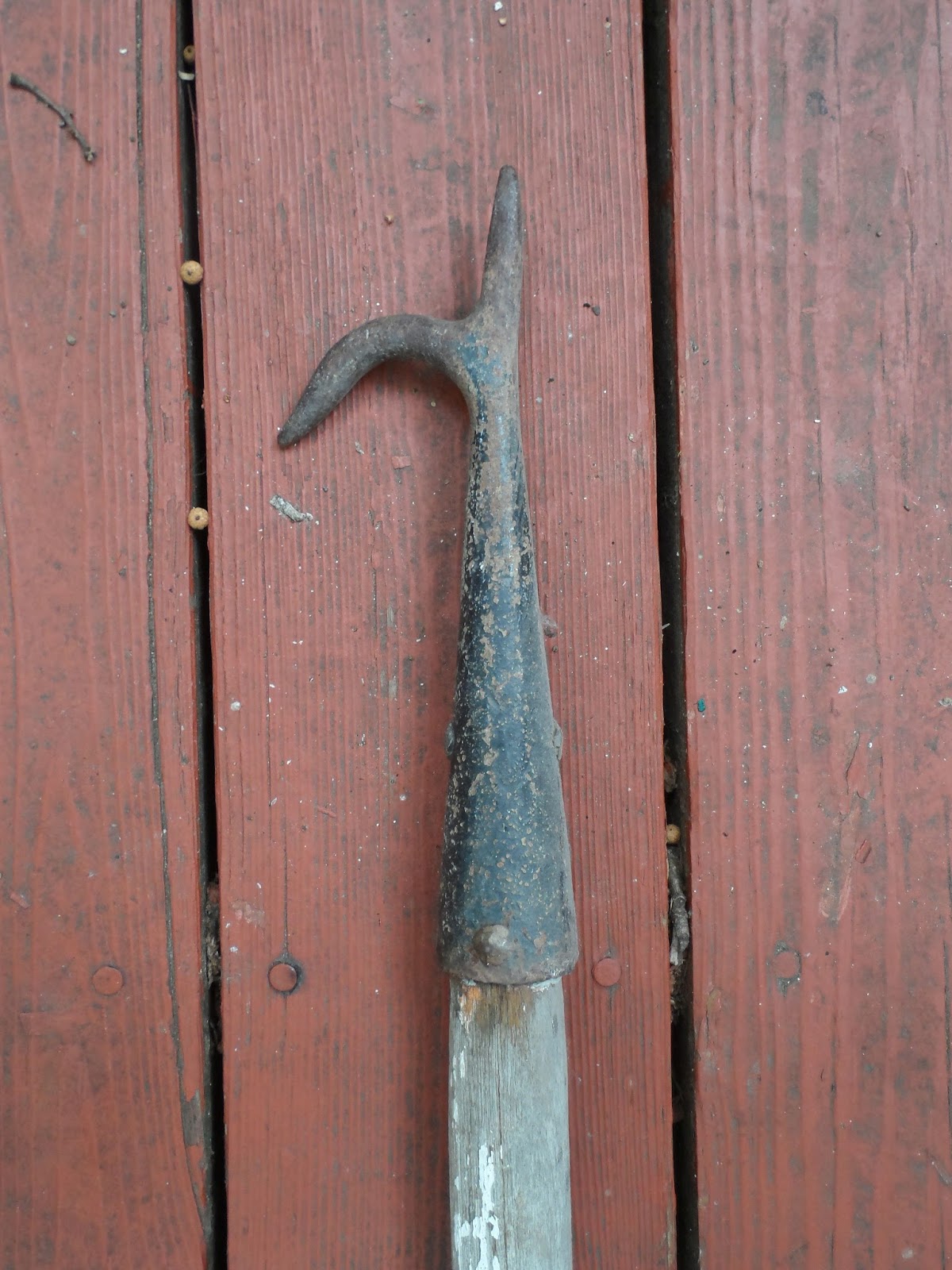
How about this classic crabber's hook? It's been hanging on the wall in my daughter's room for years, after I found it tangled up in my docklines after Isabel (I left in on the dock for 2 weeks, but no one claimed it). In fact, it was perhaps the best balanced and most suitable for all-day heavy use. No surprise.
The old guard vs. the new kids. Second from the left is my every-day pole.
I wonder who got the bright idea that a boat hook makes a good brush pole (I'm not picking on West Marine--they are ALL like that now)? All it does is snag lines. Unfortunately, about 1/2 of them won't screw into a brush because part of the hook is in the way. And nothing can be screwed into the "take" part of the hook anyway, so what's up with threads there? Worst of all...
... the bulbous padded tip makes them useless for snagging a line off a piling or dock...
Which all of the old-school poles can do easily, but only ONE of the new poles. Not an improvement in my opinion.
Showing posts with label tools. Show all posts
Showing posts with label tools. Show all posts
Tuesday, October 11, 2016
Boat Hooks
Over at Sail Delmarva, Drew has some comments on that ubiquitous tool: the boat hook


Tuesday, May 3, 2016
Making It Bigger
This post originally appeared on Windborne in Puget Sound
If you do your own boat work, there is a situation that you have undoubtedly faced: making a hole bigger. That sounds trivial until you are faced with a 1.5" hole in your hull that needs to be 2"... say to install an upgraded speedo sensor like I had to do way back in 2005.
Back then, the only way I saw to make the hole larger was to epoxy a wooden plug into the existing hole and then drill a new one, with the hole saw pilot bit cutting into that wooden plug. That worked fine but was messy and time consuming (yard time = $$).
As in most cases, whenever you stub your toe you need to view this as an opportunity. Someone has. Multiple someones in fact. Enter the hole enlarger:

This tool is really quite simple - the nut that holds the hole saw on the mandrel is replaced with a nut that has its own mandrel, allowing a second (smaller) hole saw to be mounted inside the main one. Because the fancy nut is made in such a way that the inner hole saw protrudes beyond the primary hole saw, it acts as the pilot. To enlarge a hole, you install the new larger size saw on the primary mandrel, and a saw matching the size of the existing hole as the inner saw. Simple, really, now that you see it.
These are available from Bosch, Vermont American, and even Sears. You should be able to find one for less than $20... I paid $4.95 for mine.
Tuesday, April 19, 2016
Ditch the Bent Nail
Drew at Sail Delmarva has a new take on an old method:
I've been doing a series of tests on backing plate materials, drilling, de-coring, de-epoxy filling, and re-drilling innumerable holes in balsa cored laminate. The standard method is to use a bent nail to pulverized the balsa.
Bent nail
Well, ditch that. At the suggestion of another DIY sailor I tired a notched roofing nail.
- The drill bucks less. Particularly helpful on larger holes.
- The dust is finer and hence easier to remove. No need to dig it out with a nail.
- You are less likely to miss a spot, though as the pictures show, both methods can do a very nice job.
Notched roofing nail
Dremel cutters work, producing fine dust that is easier to remove, but the undercut is only 0.09-inch vs 0.19-inch for the bent nail or roofing nail. By the time you cut a bevel for sealant, there isn't much left for a seal.
---------
The right tool for the job bay be the notched roofing nail


Tuesday, April 12, 2016
Autopilot Pump Rebuild
Today Sean and Louise, who live aboard m/v Odyssey, give us a lesson on just how effectively ingenuity and hand-held tools can substitute for the services of a machine shop.This is a post we all should read.
As I promised earlier, I'm writing up the autopilot repair in this separate post, now that we're safely anchored off Fort Macon, near Beaufort, North Carolina (map). I won't cover anything else here, so if you're not interested in the repair you can skip the remainder of the post.
By contrast, if you landed on this post from somewhere else, a little background is in order. Vector has a hydraulic steering system, with most of the components coming from the Canadian firm Jastram. That steering system includes a pair of big hydraulic rams that move the tiller arms and thus the rudder, two manual helm pumps operated by big 30"-diameter "destroyer-style" helm wheels, and an electric helm pump connected to an electronic autopilot. There are also two rudder feedback senders, one made by Jastram that drives an analog gauge on the helm console, and a second that is part of the autopilot system.
The autopilot is a Simrad unit common on boats of Vector's era, developed by Robertson, whom Simrad purchased before themselves being absorbed into Navico. Other than some water intrusion into the flybridge control head, the Simrad system has worked reasonably well since we got the boat, and we're quite happy with it. The main control unit, which nowadays would be called a computer but when this system was released was called a "junction box," a J300X model, has several output terminals to drive a variety of electric helm pumps, although Simrad also sold their own version. We have two control heads for the system, an AP20 in the pilothouse and the smaller AP22 on the flybridge.
There's really nothing at all wrong with the Simrad part of the system. It's an older unit and sometimes it misses or misconstrues NMEA inputs from the chartplotter computer, which tells it where to go in navigation mode, and when such an event starts to send us off in an odd direction we'll often say "go home, Otto, you're drunk." Typically, disengaging and re-engaging navigation mode is all that is required to get past these rare glitches.
The Jastram pump has also run more or less flawlessly until a week ago, when it quit briefly on our way into the Alligator river, and then again permanently while crossing the Pamlico the following day. Given its complexity, there are quite a number of ways in which it can fail, and several of those are electrical or electronic in nature. My first impulse was to start taking apart its integral electrical control box and put a meter on the various signals from the autopilot control unit to see if the commands were even coming through, or if either the thermal circuit breaker or the motor solenoid was not passing power through to the motor.
Motor end cap, full of carbon dust. You can see bits of the commutator in the dust.
That diagnosis revealed in short order that power was going to the motor but the motor was not turning, and removing the motor end cap, which can be done with the motor still attached, quickly revealed why: the commutator had disintegrated. The end cap was nearly packed full of dust from the carbon brushes, and I found bits of the commutator in the dust. Reluctantly, we diverted our course and put into port, hand steering for some eight hours or so.
The commutator end of the armature, still in the motor housing. You can see in-place commutator pads on the left, and missing spots on the right. And more dust.
After deciding to make port in New Bern, NC, I called three different electric motor repair places there. Upon explaining the problem, each told me the motor was not really repairable and would need to be replaced. Each also told me that without the specifications, they could not match anything up to provide a replacement motor. Thus started a lengthy Internet search for either a replacement motor, or an entire autopilot pump.
Some of the broken bits of commutator. No way to reattach these.
In the process of trying to source a motor and/or a whole pump, I learned a great deal about autopilot pumps in general and ours in particular. Now that I know it, it all makes perfect sense, but it's not something I had to think about before.
Our pump is a constant-running pump with a "shuttle valve" or "pilot valve" attached. When the autopilot is engaged, the pump runs continuously and in one direction only. Absent any commands, the fluid leaves the pump and immediately returns via a U-turn in the center of the pilot valve. When the autopilot commands right or left rudder, the shuttle moves in a corresponding direction to send the fluid into the helm lines leading to the ram cylinders in one direction or the other; from the point of view of the valve, this is either a "straight through" or "crossed over" arrangement of the output.
The cover plate from the shuttle valve, showing the fluid flow diagram.
When I started looking into replacement autopilot pumps, the vast majority on the market were not constant-running pumps with shuttle valves, but, rather, reversible pumps. The pump is plumbed directly to the steering lines, and the motor is operated in one direction or the other, by changing polarity, to move the rudder, which stops when there is no power sent to the pump at all. Unsurprisingly, these types of pumps, being much simpler in design, were considerably less expensive than the constant-running types.
Upon further investigation I learned that autopilot pumps, while often sold in catalogs based on boat length, are really sized instead by the volume of the steering ram(s). When you think about it, this makes perfect sense: the pump needs to be able to take the rudder from full left to full right in a set amount of time; 20 seconds is a typical number for automatic operation; half that or less might be required if "manual" steering will be done by means of a follow-up lever. How long it takes the pump to move the rudder is a function of the flow rate of the pump and the volume of the steering ram(s).
Vector has two steering rams with a capacity of 300cc apiece. That means that 600cc must flow through the system to move the rudder from full lock right to full lock left or vice versa. The Jastram pump installed with the system is a 3 liter/minute pump, or a lock-to-lock time of about 20 seconds. By contrast, the largest reversible pump I found, at around $900, was rated for 2 liters/minute, and pumps in the $500 range were more like 1 liter/minute. None of those was going to cut it with our system, and 3 liter/minute pumps, all of which are the constant running type with shuttle valve, are in the $3,000 range. Learning this gave me great incentive to repair the pump we already had.
Somewhere in the process of this research, I learned that a now-discontinued reversible pump, made by Accu-Steer, is the underpinning of our pump. Jastram partnered with Accu-Steer and mated a valve block and a Vickers shuttle valve to their HRP-75 pump to create the Jastram HPU-180 pump, then hard-wired the motor to run in a single, continuous direction. I was able to find a replacement HRP-75 on eBay (which I later purchased as a spare; we should have it in a couple of weeks) and deduce some things about the motor from a partial nameplate in the listing photo.
Between that, the physical characteristics of the existing motor and pump, and the limited specs in my owner manual, I guessed that a 1/7-HP rated motor turning around 1,700 rpm at 12 volts would be sufficient for the task. Motors of about this specification, but with square rather than round end-plates, are available on short notice from Grainger for about $270 or McMaster-Carr for about $190. In either case, I'd have to modify the mounts, but, more importantly, find a way to couple their 1/2" output shafts to the pump's 3/8" input coupling.
After hunting around for quite some time, I came across this motor available on Amazon for just $50 with free two-day Prime shipping. It's rated at 3,800rpm at 24v, or half that at 12v, with the required 150-watt continuous rating. It's significantly smaller physically than the motor it's replacing, which gave me pause, and I knew I'd have to find some way to mount it with its smaller end-cap, as well as adapt its 5/16" output shaft to the 3/8" pump input.
Old motor at left with new one at right. Note the machined lip on the old motor and the four mounting holes on the end cap; in this photo the new motor has already been drilled and tapped for the same mount and "machined" down to the same OD.
With a replacement pump/motor assembly on tap via eBay and nothing to lose, I ordered the motor on Amazon with a delivery for Tuesday afternoon. As soon as it arrived, I set to work. After a quick test to ensure the motor spun properly in both directions, I started on the output shaft adapter. This started out as a length of 3/8" OD, ~5/16 ID copper tubing, less than a dollar for 3" worth at the hardware store in town.
It's impossible to cut a clean end on soft copper tubing, so I had to run my 5/6" drill bit through the tube a few times to get the motor shaft to fit. This after over an hour of fiddling to remove the belt pulley that came with the motor, which, despite being putatively retained by a simple clip ring, was effectively press-welded to the shaft. (I ended up hacksawing it in pieces and then running the motor against a bastard file until the stupid thing fell off.)
Lovejoy-type coupler with the home-made copper reducer fitting inserted.
Once I had the tubing pressed over the shaft on a close fit, I spun the motor up, tubing and all, to cut the tubing to length against a sharp file, then spun it some more against first a file and then an emery cloth until the tubing fit snugly inside the 3/8" Lovejoy-style coupling (actually a Martin brand coupling) that came off the old motor. I then drilled a small hole in the tubing for the set-screw on the coupling to pass through and engage the flat on the new shaft.
With the tubing and Martin coupler in place, I held the motor up against the mating coupler on the pump by hand, while Louise operated the autopilot's non-follow-up mode to move the rudder from full left to full right and back again. I expected to have to grip the motor tightly, but was pleasantly surprised by how little torque was required to keep it in place. The little motor had no trouble moving the rudder, at least at the dock with no water flow past it.
New motor with jaw coupling installed, ready for installation.
That accomplished, the next step was to mate the motor to the pump in some sort of permanent way. The previous motor was affixed with four 10-32 machine screws near the outboard edge of the end cap. The new motor was drilled and tapped for three 10-32 screws a good deal closer to center. Ideally I would be able to use these mounting holes, but the connection to the pump involved a flanged tube wherein the tube portion was very nearly on top of those threaded holes. There was no way to drill the flange for the new bolt holes or get bolts in to them.
Instead I opted to disassemble the brand new motor so that I had the end cap as a loose part, then drill and tap the end cap for the four 10-32 bolts in their original locations. The casting of the inside portion of the end cap made that nearly impossible, and I managed to get two good holes and two somewhat oblong ones, but with usable 10-32 threads nonetheless.
My hokey mounting holes, near the outboard edge of the end cap. The OEM mounting holes, closer to the spindle, are tapped into thicker ribs cast into the end cap for the purpose. I made sure that one new mounting hole, at lower right, also ended up in a thicker part of the casting.
The old motor had a machined lip on the end cap that mated with a lip on the mounting flange. The new motor's entire end cap was just a hair over the diameter of this machined lip, so I put a bolt through the spindle hole, chucked the end cap in my drill, and spun it against a file until the OD just fit inside the lip on the mounting flange. Crude, but it worked.
Once it was all in place and bolted together, we fired up the autopilot and ran the rudder in both directions several times. Other than being a bit quieter than the old motor, we could detect no real difference in performance, but, again, that's at the dock with no water flow. We knew we'd need a sea trial.
Today's cruise down the Neuse River and Adams Creek provided the first real test. It all seems to be working fine, and we made it do several hard-over turns at our normal cruising speed to be sure the new motor would not bog down. Again, other than being quieter, which I attribute to the commutator problems on the old unit, we can't tell the difference. Only time will tell if this inexpensive motor will live up to the challenge.
The new motor does not have externally accessible brushes, so if those need replacing I will need to open it up and do some soldering. But then again, the externally replaceable brushes on the old motor did no good at all -- the brushes still had plenty of meat left when the commutator self-destructed. If this motor burns up in a couple of years, I'll just buy another one for another $50. As it stands now, I have a total of about $55 invested in the repair.
I did buy a 1/2" hub Martin coupling for a few bucks, in case I need to upgrade to the aforementioned motors from either McMaster or Grainger. Those motors can be had in a day or two, so having the coupling on hand will make the swap that much quicker. And I also blew ten bucks on a package of spindle bushings to mate 1/4" shafts to 3/8" couplers, in case I need to change to a motor with a 1/4" spindle. Between the two of them, I should be able to get a workable replacement motor up and running in just a couple of days anywhere we might be, should the current hack quit working.
As I mentioned earlier, I also ordered a used take-out Accu-Steer HRP-75 pump assembly. This should have a good working motor on it as well as the swash-plate pump itself, giving me spares for most of the moving parts of the Jastram pump. The other moving part is the pilot valve, readily available from Eaton/Vickers in stock. I spent just $150 on this used pump, inclusive of shipping, and for that price I'm happy to have the spares even if I never need them.
Tomorrow we will head out into the ocean on an overnight passage, which will be the real litmus test of my repair. I have no reason to believe it will not work perfectly, but the diminutive size of the replacement motor will have me watching it closely for the next few passages.


Tuesday, May 5, 2015
How much is it?
This post originally appeared on Windborne in Puget Sound
I recently did a post which talked about establishing what the right amount of glycol in a holding plate solution was. Well, OK, now that we know what we want to have in there, how do we determine what we actually have? I suppose one possibility would be to simply empty the holding plate and refill it with a solution of known concentration, one that we just made up by careful measuring. Yeah, that would work.
But what if we just want to add a little water or glycol to what we already have? For that we would need to be able to measure the concentration in the solution.
This is the tool for that: It is a refractometer - it measures the refractive index of a liquid.
What is that?
All transparent substances slow the passage of light thru them somewhat - some more than others. The refractive index is the ratio of the speed of light in a vacuum compared to the speed of light in the transparent substance. So, if I tell you that the refractive index of a particular glass is 1.33, that means that, yes, light travels thru that glass only 3/4 as fast as in a vacuum. You have witnessed refractive index differences when you, for example, mixed water and vodka, or dove in a place where fresh water and salt water are mixing (at Shilshole, for example).
But for our purposes, it is enough to know that the refractive index of a water/propylene glycol mixture changes in a predictable way with the concentration of glycol. We don't even have to know the details of that change because the manufacturer has taken that into account in the preparation of the scale inside the instrument.
All that remains is for us to obtain a drop or two of the solution and put it onto the prism covered by the clear plastic flap, and look thru the lens at the other end of the instrument, for a view like this:
But there is a catch (isn't there always?). Before I sample the holding tank solution, I have to completely defrost the freezer. If I don't, some unknown quantity of the water in the system will be frozen out, which would skew the results in the direction of increasing concentration. So the refractometer stands ready for duty, waiting for a freezer defrost event.
Who knows when that will be?
But what if we just want to add a little water or glycol to what we already have? For that we would need to be able to measure the concentration in the solution.
 |
| Hand-held refractometer |
What is that?
All transparent substances slow the passage of light thru them somewhat - some more than others. The refractive index is the ratio of the speed of light in a vacuum compared to the speed of light in the transparent substance. So, if I tell you that the refractive index of a particular glass is 1.33, that means that, yes, light travels thru that glass only 3/4 as fast as in a vacuum. You have witnessed refractive index differences when you, for example, mixed water and vodka, or dove in a place where fresh water and salt water are mixing (at Shilshole, for example).
But for our purposes, it is enough to know that the refractive index of a water/propylene glycol mixture changes in a predictable way with the concentration of glycol. We don't even have to know the details of that change because the manufacturer has taken that into account in the preparation of the scale inside the instrument.
All that remains is for us to obtain a drop or two of the solution and put it onto the prism covered by the clear plastic flap, and look thru the lens at the other end of the instrument, for a view like this:
 |
| Approximately 33% propylene glycol shown |
Who knows when that will be?
Tuesday, January 13, 2015
Creating the Right Tool for the Job
My father encouraged me to always use the right tool for the job. But what do you do when there is no such tool? Well, then you make one. At least that's what Jeff on s/v Pilgrim does.
(Jeff and Anne are completely reconstructing Pilgrim, virtually from the hull out - most of their work is far too extensive to include here, but I encourage you to visit their website to see it.)
(Jeff and Anne are completely reconstructing Pilgrim, virtually from the hull out - most of their work is far too extensive to include here, but I encourage you to visit their website to see it.)
Any wrench large enough to fit the packing nut on Pilgrim’s possessed a handle too long to fit into the tight confines of the hull.
Looking down the rudder shaft at the packing nut.
Deep gouges along the upper edge of the nut indicated a hammer and cold chisel were used to tighten the nut. Curiously no such evidence of similarly brutal tactics use to loosen the nut are evident. Could it be that Pilgrim’s rudder packing is original?
Rather than attack the nut with hammer and chisel, I elected to create the proper tool for the job.
Creating a plywood template of the ideal tool for the job.
Using 1/8” luan plywood and some trial and error I created a pattern for the ideal M382 rudder post packing nut wrench. Once satisfied with the design, I transferred the pattern to a fresh piece of plywood
Transferring the rough, initial template to a fresh piece of plywood.
A query around the commercial fishing fleet portion of the boat yard yielded a free piece of sufficiently sized 3/8” steel.
Next stop Lindow’s Machine Shop on Hwy 70 outside of Beaufort, NC. Yup that is right... a straight up plug for Lindow’s. Fred Lindow, owner and sole employee, has many years of personal experience on sailboats. He does excellent work at reasonable prices. Fred transferred the template to the metal, and then used a band saw to cut out the wrench.
Wrench clamped in vice while I clean up the rough edges with a file.
Back at the boat yard, I cleaned up the sharp edges with a file and applied a few coats of red paint.
Ready to remove the nut.
Now possessing the right tool for the job it is time to remove the packing nut.
Happiness is having the right tools for the job.
The short wrench handle and awkward body position limited the torque I could physically apply to the nut. Ultimately removing the nut did require striking the handle of the wrench with a mallet -far preferable to further damaging the nut with blows from a cold chisel.
Removing the old packing material.
Using a combination of picks and a small flat screw driver, I excavated decaying, flax packing from the nut. Based on the condition of the packing material I would not be surprised if it is from the original 1979 construction. I have little doubt it was leaking when submerged.
Close up of gouges along the upper edge of Pilgrim's rudder packing nut.
A few minutes with the bench grinder’s wire wheel and the packing nut cleaned up nicely. Despite the deep gouges along the upper edge, I do believe it remains serviceable.
Next step is to lift the boat high enough for the rudder post to clear the hull. Hmm – I wonder how much that rudder weighs?
Our Rudder Repairs and Modifications Photo Album contains additional images and notes from this ongoing project.


Tuesday, September 16, 2014
Dock Box Carpentry
Given Norm Abram's shop, getting really good results from wood working projects is relatively easy. But doing it on the dock, with a very limited set of tools that all have to go in the dock box when you are done... not so much. As promised, here is Walt on s/v Suppose's post on "Dock Box Carpentry". He makes it look easy:
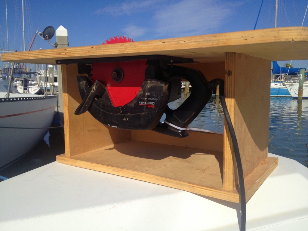
There was a time when I had an oversized garage with a table saw and a long workbench with a drill press, belt sander, vise and rows of drawers filled with a variety of tools. Now, instead of a garage, we have a dock box and the trunk of our car. I thought that there might be some interest in the simplified set of tools that I am using, a cordless drill, circular saw and router.
This is my combination table saw and router table. It is a simple plywood construction shown with the circular saw mounted underneath. The trigger on the saw is not easily accessible or lockable. So, I strapped it down with a tie wrap and the saw is turned on and off by plugging and unplugging the power cord. I know that this is unsafe on a variety of levels but knowing that is exactly what makes me doubly cautious. Plus, the circular saw is not nearly as powerful as a real table saw and not as likely to kick back violently. So far, I have had no accidents or even a close call.
I mounted the saw under the table such that the edge of the saw's base is parallel to the table edge. After making a plunge cut to bring the blade through the table top, I laid a guideline the full length of the table that is aligned with the side of the blade. I measure and make marks relative to the guideline at both ends of the table and clamp a board on the marks to serve as a rip fence. It's a little tedious but works very well.
A piece of half inch plywood screwed at a 90 degree angle to a 1x2 inch rail that rides against the edge of the table makes a usable mitre guide. I added a strip of wood to the top to clamp stop blocks for repeated cuts.
This the same table with the router mounted underneath. The clamped on fence and miter guide are useful with the router as well. With a 1/2x1 inch straight bit and 1/4 and 1/2 inch quarter-round bits, I can make all of the joints and decorative cuts that I need for boat projects.
This is my favorite new tool, a portable drill press. Our rigger let me use the real drill press in his shop to drill a variety of holes through a 3/4x2 inch strip of teak which I use as a drilling guide.
There is something about my "no line" glasses that makes it impossible for me to line the drill up for a hole perpendicular to a surface. The drilling guide is a huge help.
This is another indispensable tool that I use often. Many times, the most difficult part of a job is just getting the workpiece to stay put while you hammer, drill or file on it. A solid vice can be a life saver. This one is mounted a 1 1/2 inch ash board. The board has feet at both ends so that work can be clamped directly to the board as well as in the vice.
For me, the key to getting reasonably accurate work is to build a jig for everything. This a drilling jig that I used to locate the holes for hinge pins in a spice rack project.
With patience (the really hard part), you can finish projects that you can be happy with, even though the tools that you are using are limited.


Wednesday, March 19, 2014
Curing oven
Ever want to speed up epoxy hardening? Or 5200? Because time is money, manufacturers use curing ovens to save time. But how can the savvy boater do it? Are we doomed forever to wait for the slow cure? Over at Sail Delmarva Drew has an answer.
Numerous times I have post-cured epoxy projects or hurried alone some small painted object by placing it in the kitchen oven set to "warm." The object would be dry already, but probably not so well cured as I would like by the weekend, and a few hours at 150F can work wonders, reducing chipping on new paint and bringing epoxy to full strength. It always causes a little disruption to havea project in the oven.
Another common problem, at least for northern sailors, is to get polyurethane adhesives and caulks to cure in the winter. Even if we take them inside where it's warm, they just don't cure. The problems is that polyurethanes require moisture to cure, just as epoxy requires a "part b," and a heated home is desert dry, the RH typically below 40%.
When I started to repair the exploded hiking boots with polyurethane adhesive, particularly because of the thick application. I knew I would need a very warm humid cure. Because om my work with mold and mildew for Practical Sailor, the solution was obvious.
A heating pad on medium seemed about right, but it has 3 settings. Generally it is better to have a gel cure before going in; the higher temperatures can make paint and epoxy sag.
If humidity is required, add a damp towel.
Bingo. By adding humidity, sealants like 3M 5200 can be pushed in 12-36 hours instead of a week or more. If dry curing is the goal, skip the damp towel. In the photo I had polyurethane coated some straps, but only in the center for wear resistance; by trapping them in the lid they don't touch anything and were cured in the morning.
If some things are so bloody obvious, why does it take us so long to figure them out?

Tuesday, March 11, 2014
Oooo... Shiny...
This post originally appeared on Windborne in Puget Sound
In an earlier post I bemoaned the passing of the "good" Brasso. These two posts were not unrelated, because Eolian's wheel has a bronze hub. And that hub periodically gets treated to a polishing with Brasso.
But in this post I referred in passing to the use of a buffing wheel as the tool of choice when polishing metal, and I realized that some of the readers of this blog might not know what a simple, basic and effective tool it is for polishing metal.
If you have a grinder, then you could have a buffing wheel. Get thee to a Harbor Freight or whatever your local cheap tool emporium is, and buy yourself a couple buffing wheels - these are made by stacking multiple canvas disks together until you have a combined thickness of about ½", and then sewing them together. Here I have removed one grinding wheel from my grinder and replaced it with a buffing wheel.
You'll also need compound - the cloth alone is not enough. That orangish pink bar on the work bench right below the buffing wheel is a bar of rouge. Well, more accurately, it is a bar of rouge polishing compound. Rouge is a very fine iron oxide powder; the compound is a suspension of rouge in a wax base. You hold it against the spinning wheel for a moment to charge the wheel, and then you apply the piece of metal to the wheel. You'll have no difficulty in telling when more compound is needed, because the wheel will simply stop polishing.
Rouge is not the only polishing compound - in fact it is the last and final step when starting with raw, heavily oxidized and rough metal. But for lightly oxidized brass or bronze, it is ideal. Oh, and you should not mix compounds on a wheel - get one wheel for each type of compound you buy.
When applying the metal piece to the wheel, you must think about what is happening. You must be very careful to not let the rapidly spinning wheel catch on any edge - if it does, it will grab the piece right out of your hands and throw it against the wall, probably damaging the piece, the wall, and possibly your hands in the process. Also, since the wheel is continuously shedding threads - you absolutely must wear safety goggles. If you are working on a small piece, it will rapidly get too hot to hold. Wearing a pair of heavy leather work gloves is a good idea.
It is quick and easy to get a factory finish on a piece of metal using a buffing wheel - because this is how the factory polishes metal!
(I've seen attachments for an electric drill to hold a buffing wheel. These are not effective because the drill does not turn fast enough. But I have chucked a buffing wheel onto an angle grinder to work on pieces that I cannot take to the grinder - this works well.)
 |
| Dull. Boring. |
In an earlier post I bemoaned the passing of the "good" Brasso. These two posts were not unrelated, because Eolian's wheel has a bronze hub. And that hub periodically gets treated to a polishing with Brasso.
But in this post I referred in passing to the use of a buffing wheel as the tool of choice when polishing metal, and I realized that some of the readers of this blog might not know what a simple, basic and effective tool it is for polishing metal.
 |
| The tools |
You'll also need compound - the cloth alone is not enough. That orangish pink bar on the work bench right below the buffing wheel is a bar of rouge. Well, more accurately, it is a bar of rouge polishing compound. Rouge is a very fine iron oxide powder; the compound is a suspension of rouge in a wax base. You hold it against the spinning wheel for a moment to charge the wheel, and then you apply the piece of metal to the wheel. You'll have no difficulty in telling when more compound is needed, because the wheel will simply stop polishing.
 |
| (I should be using two hands, but then how would I take the picture?) |
When applying the metal piece to the wheel, you must think about what is happening. You must be very careful to not let the rapidly spinning wheel catch on any edge - if it does, it will grab the piece right out of your hands and throw it against the wall, probably damaging the piece, the wall, and possibly your hands in the process. Also, since the wheel is continuously shedding threads - you absolutely must wear safety goggles. If you are working on a small piece, it will rapidly get too hot to hold. Wearing a pair of heavy leather work gloves is a good idea.
 |
| Ten Minutes: Ta DAA! |
(I've seen attachments for an electric drill to hold a buffing wheel. These are not effective because the drill does not turn fast enough. But I have chucked a buffing wheel onto an angle grinder to work on pieces that I cannot take to the grinder - this works well.)
Thursday, January 30, 2014
Tie shooter
This post originally appeared on Windborne in Puget Sound
It's not an expensive tool - I'm sure I paid less than $10 for mine, but it was an impulse buy (too many of my tool purchases are...) and I don't remember where I got it any more. But here are some available today that I found on the Intertubes:
 |
| (I wonder how many folks ended up here because they were looking for some Star Wars© related toy) |
- Zip ties,
- Tie-wraps,
- Wire ties,
- Cable ties,
- Nylon ties,
- Panduits (if you work for the Boeing company)...
Whatever you call them - they're all the same thing. And I know you have them on board - every boat does. In fact you probably have a stash of them, ready to hand. They are so handy that they get used for everything. They're probably right there next to your duct tape.
That's where this tool comes in - it can pull the ties a lot tighter than you can by hand, and it cuts them off almost flush with the retainer/ratchet gizmo. The little red knob is an adjustment for the tension that is applied - the tool is strong enough to break the smaller wire tires if the tension is all the way up.
- http://www.uline.com/Product/Detail/H-241/Cable-Tie-Guns-Mounts/Economy-Cable-Tie-Gun, $16. This looks like mine, but I'm sure I paid less than this
- http://www.amazon.com/Eastwood-Professional-Cable-Wire-Tie/dp/B006ISG5M0/ref=pd_sim_sbs_auto_1, $14.99. This one looks like a better tool than mine
- http://www.amazon.com/Electra-Force-89605-Automotive-Tension-Settings/dp/B002CWPYBO/ref=pd_sim_sbs_auto_4, $6.95
Tuesday, November 12, 2013
Extension Cords
Extension cords are a pain. They seem to tangle themselves into knots when they are unsupervised in a locker somewhere. Scott on s/v Valkier has a suggestion...
So someone asked me about what I use for an extension cord on the boat because of a comment I had made about having the perfect one. Everyone knows what a pain extension cords are. They are constantly getting tangled and snarled up, they are a pain to coil back up after using them, they are a pain to un-snarl and pull them out of the cockpit locker after they have become wrapped around every other thing in there. Last but not least is that you can only plug one thing into a standard extension cord. I am constantly having to switch between a drill and a sander or router etc… It just slows stuff down.
How it came about is a long story… lol… not!!!
One day I was in a tool store, not sure where, and saw one of the extension cords in a reel box with 4 outlets built into the box. It was on sale and I thought wow, I need to try that out it would be great on the boat. It has been about a year since that day and it has been everything that I thought it would be and more. The one I got was cheap and I wondered about life span but it is battered and still going strong. Mostly what it has done for me is alleviated a lot of frustration due to the above listed downsides to standard extension cords. It also means that I am more likely to grab stuff to do a quicky project because it is easier to un-spool cable and re-spool it when done. Less time in setup and clean up on both ends of the project. Mine is 25ft in length and I think I want one 50ft and one cable size bigger. However I would bet that I mostly keep using the 25ft one due to size. A 50ft cord and reel will be substantially larger.
Friday, October 25, 2013
A fairly exclusive club
Here on Eolian, we have joined a fairly exclusive club - owners of Sailrite's walking-foot sewing machines.
Our cockpit canvas, custom-made for us at great expense 9 years ago is starting to come apart. The thread is failing. When we had the canvas made, the tradesman (Barrett Enclosures) asked us if we wanted to use the very expensive Tenara thread, or the regular UV-stabilized polyester. Given that the Tenara cost more than $100/spool and that the Sunbrella itself is UV stabilized polyester, we selected the less expensive thread.
Tho the Sunbrella is clearly aging, it has years to go. But the thread has failed on all of the horizontal surfaces. I have been stitching it back in with a hand stitcher, but this is extremely tedious, and it is difficult to do a good job. And we have lost four zippers to UV exposure, so far.
So I have been on the lookout for a sewing machine capable of sewing multiple layers of heavy canvas. A couple of weeks ago, I responded to a craigslist ad and bought a used Sailrite LSZ-1. This is a walking foot machine: the presser foot on top of the fabric moves, at the same time and for the same distance as the feed dogs on the bottom of the fabric. Your standard home-owner machine has a stationary presser foot, which means that with multiple layers of fabric, the top-most layers tend to be dragged back by the stationary presser foot, causing the seam to pucker and curl. The LSZ-1 also has a powerful double gear reduction drive. How powerful you ask?
This machine is a monster. Here you see 8 layers of heavy Sunbrella that I sewed across - the machine didn't even break a sweat. It just went ker-chunk, ker-chunk, ker-chunk, with no hesitation and no manual persuading from me - like it was sewing butter. This is not your Mama's sewing machine.
So I am now busy re-stitching all of our canvas. And yes, I did spend the $$$ for a spool of the lifetime warranted fluorocarbon thread. I wish I had done that 9 years ago.
But then if I had, I wouldn't be learning the trade of cockpit tailor.
 | |
| Sailrite LSZ-1 |
Big Mistake.
Tho the Sunbrella is clearly aging, it has years to go. But the thread has failed on all of the horizontal surfaces. I have been stitching it back in with a hand stitcher, but this is extremely tedious, and it is difficult to do a good job. And we have lost four zippers to UV exposure, so far.
So I have been on the lookout for a sewing machine capable of sewing multiple layers of heavy canvas. A couple of weeks ago, I responded to a craigslist ad and bought a used Sailrite LSZ-1. This is a walking foot machine: the presser foot on top of the fabric moves, at the same time and for the same distance as the feed dogs on the bottom of the fabric. Your standard home-owner machine has a stationary presser foot, which means that with multiple layers of fabric, the top-most layers tend to be dragged back by the stationary presser foot, causing the seam to pucker and curl. The LSZ-1 also has a powerful double gear reduction drive. How powerful you ask?
 |
| Eight layers of Sunbrella: with ease |
This machine is a monster. Here you see 8 layers of heavy Sunbrella that I sewed across - the machine didn't even break a sweat. It just went ker-chunk, ker-chunk, ker-chunk, with no hesitation and no manual persuading from me - like it was sewing butter. This is not your Mama's sewing machine.
So I am now busy re-stitching all of our canvas. And yes, I did spend the $$$ for a spool of the lifetime warranted fluorocarbon thread. I wish I had done that 9 years ago.
But then if I had, I wouldn't be learning the trade of cockpit tailor.
Tuesday, August 20, 2013
Low-Buck Project: Rig Tuning
Does your mast flop back and forth when you tack? Or is your rigging set up so tight that it is turning the boat into a banana? Over at Dock Six, Brian tackles the issue and shows us a tool that anyone with a big stick held up with wires on their boat should probably have...
"Welcome to a new kind of tension..."
-Green Day
A Friend of the Dock, Rod (Henceforth known as FOD Rod), is one of those boaters that we all know.
Or wish we knew.
Or hope to know.
He's owned sailboats and powerboats and been comfortable on each, has run big boats and small boats, been a yacht club member and a dock rat, and has not developed, (or maybe lost) any prejudices regarding size, mode of propulsion or affiliation. Over more than three decades, he's been there, done that... quietly. He doesn't steer a barstool and try to command a room, he'd rather be polishing, or fixing or sailing his Catalina or piloting his Limestone.
Along the way he's amassed some of the gear that we all wish we had, have thought about buying, or didn't even realize existed.
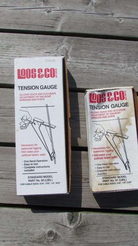
Like Loos Gauges.
One of the endlessly interesting (or numblingly, observing-paint-dryingly boring, depending) aspects of sailing is the myriad infinite adjustments that can be made to a sailboat's rig, and the effect that the rig tension has on performance. Some sailors like a loose rig, believing that it relieves strain on the mast step and compression post, others prefer a rig that is tight as a drum port-starboard, but with a lot of fore-aft adjustability, others like tight stays with loose shrouds, etc.,
Me? I've always tuned my rig by eye and by ear. Tighten up the backstay until the forestay is tight and the mast has a nice rake, then tighten the lower shrouds until they all give me the same note when twanged, then do the same thing with the upper shrouds.
(I like the upper shrouds to sound a half tone to a tone lower than the lower shrouds, but then, I like a lot of bass.)
It always seemed okay to me, but I wondered- am I, maybe, overtightening or undertightening my rig? should I be concerned about a catastrohic failure, or could I maybe find another 1/10th of a knot and less weather helm if I cranked the turnbuckles another turn or two?
FOD Rod mentioned that he, of course, had the tools for this, and kindly loaned me his Loos gauges.
The process is simple, and takes little time. The tools required are just as simple:
The gauge, and the tools you use to adjust your turnbuckles.
Testing tension is just plain stupid simple. Clip the gauge to the stay or shroud....
Pull the lanyard until the pointer reaches the black line....
... and note the number at the middle of the stay/shroud .
Included with the Loos Gauge is an instruction leaflet, which includes a conversion chart for optimum tension, based on the diameter of the wire. Compare your reading to the chart, then tighten or loosen the turnbuckles accordingly, rechecking until the tension is within spec. Easy peasy.
Turns out my tuning-by-twang was pretty close. The uppers benefitted from another couple of turns on the turnbuckle, the backstay took three, the lower shrouds were spot on.
I don't know whether it has made our galleon of a pocket cruiser any faster, but it's kinda cool to know that she is as optimized rig-wise, as she can get.
Give it a try.
"Talk The Dock!"


Subscribe to:
Posts (Atom)


