About a month after buying Rubigale, and with a boat full of crew, we were ready to leave the fuel dock after a day of sailing. After pumping out I went to start the engine, turned the key, and nothing. Not even a click. I knew nothing about engines-zero, zip. I could find the alternator and the dipstick. My knowledge of cars surpassed that of boats only because I knew where to put in windsheild wiper fluid. I didn’t know how I was going to get back to my slip and had a half dozen people that needed to go home. My boat mentor J had his own boat full of crew and couldn’t help at the moment. Fortunately, T lives aboard a few docks away, and after I fished out a mystery set of wires with clips that I had found in the bowels of weird boat storage (had this happened before?), he jumpstarted the boat by connecting the battery to the start switch.
Success!
I thought the crew would disappear as soon as we were back to the slip, but J and T started troubleshooting the starter and half of the people stayed, rapt with the process. I didn’t understand much of what I was hearing, but I was mesmerized by the problem solving. I photographed where to connect the wife to the starter just in case. Final diagnosis, probably a bad starter switch because there were loose connections and a little corrosion. J showed up with a new starter the next day and showed me how to put it in. It was much easier than I had expected and I photographed that as well. As a bonus, he connected a new engine hour meter to the switch so I could keep track of hours since the previous meter had died at just under 4000 hours at some unknown point in the past. Everything seemed to work great and I put it away in my mind as a solved issue.
Showing posts with label engine. Show all posts
Showing posts with label engine. Show all posts
Tuesday, June 20, 2017
Starting A Boat With A Paperclip
This isn't a project per se... well actually it is, but the most important part of this post is the successful trouble shooting of a problem. And yes, it does invoke MacGyver-ism. Read along with Dana on s/v Rubigale, as she deals with a motor that suddenly refuses to start...


Tuesday, July 19, 2016
Changing the seal on a SD20 Yanmar saildrive
It has been said (often) that cruising is working on your boat in exotic locations. And while that is an overly pessimistic assessment, certainly cruising cannot be entirely a vacation from maintenance. While Valerie is away, Laurent on s/v Letitgo gets busy on one of those necessary tasks...
Some amazing photos will be present in this post but maybe not for all public; once the Vahine has left the surrounding of the boat, well in my dream… With that said I was left to ponder on what could be done during this sunny day. so let’s “dive” in one of the most interesting subject of all: oil and seals on a SD20 Yanmar saildrive. Please stop all the applause, I know you are excited but one day somebody will do a Google search and will find the solution to a problem a few years ago we couldn’t!
For the rest it’s just a reverse job and 5 liters of gear oil to complete the job.


Tuesday, March 10, 2015
Westerbeke 44B Glow Plug Replacement
We sailors like to pretend that we are not power boaters. But almost all of us are. And when that motor doesn't do what it is supposed to do, we are filled with anxiety. Nate and Natalie living aboard s/v Astraea got to the bottom of their engine difficulty, and found it was a straightforward problem:
The day we got Astraea the engine started right up. Then after having her for about eight months the engine started being hard to start. We thought it was a problem with the batteries not delivering enough current, and they were seven years old, so I replaced them. Well, that didn’t make the engine start any easier. Each time we went to use the engine for the first time that day it would take 2 or three long cranks to start the engine. Our engine starting procedure went something like this:
Back in December at Southwestern Yacht Club I got lucky troubleshooting when Gary from Sea Rover II came over to help. He had a clamp on ammeter that we used to check the starter current and the current through the glow plugs. We used a voltmeter to read good voltage at the rail that connects the glow plugs, but when activated there was no current drawn, indicating that the heating element in the glow plug burnt up and was and open, not allowing electricity to flow through and register as Amps.
- Open the floor boards and turn off the raw water supply so we wouldn’t flood the engine.
- Hold preheat for 10 seconds and then crank the engine for 20-30 seconds, knowing that it wouldn’t start.
- Put the batteries on “Combined” and pray the engine would start when we would crank it for 20-30 seconds. Sometimes it would, but usually it wouldn’t.
- Crank the engine one more time for 20-30 seconds and it would either start, or we’d pull out the generator and charge the batteries.
- Once the engine started, rush down and open the seacock for the raw water supply to allow cooling water through the engine.
- Check for water discharge at the stern and see that the batteries are charging.
- Sigh a sigh of relief and/or have a beer.
The day before we left San Diego I went and bought 4 new glow plugs from A to Z Marine near Shelter Island, but didn’t install them until a few weeks ago because I didn’t want to screw the engine up worse during our long cruise down the coast. I now regret not having replaced the glow plugs sooner because it was really easy.
To replace the glow plugs all I had to do was remove the rail that connects them, then back the glow plugs out and replace them and tighten like a spark plug. The most important part of the prep work was ensuring that the engine was clean to prevent anything from falling in the cylinders while working.
The glow plugs are just a bit different, if you look at the old plug there are 7 threads that were engaged in the engine. When I replaced it the new plug only went down 4 turns before it got tight. After removing and inspecting the new plug, I saw that the middle of the plug below the threads is longer on the new plug. About 4 threads are needed to engage to have the plug seat entirely.
After replacing all four plugs we just push the preheat button for about 5 seconds, then crank the engine for about a second and it fires right up! No more sweating if the engine won’t start! Natalie said she was getting an ulcer with the stress of whether or not the engine would start. Now she can worry about other things.


Friday, July 12, 2013
The right dipstick?
Mike and Rebecca of s/v Zero to Cruising are soon to move aboard a much larger boat - a Leopard 4600. This boat has a pair of diesel engines equipped with SD50 saildrives...
I’m sure it can be said that all engines have their own issues. Our last few years have been spent learning the ins and outs of outboard engines. While that info is still important as we will have a Yamaha outboard powering our tender, the Leopard that we’ll be living and working on has an entirely different setup for its auxiliary engines.
In the stern of each hull of the 4600 lies a 54HP Yanmar diesel engine. Unlike some of this boat’s Leopard predecessors, the engine is not connected directly to the propellor via a straight shaft. On the contrary, it transfers power through a couple of right angles via a system called a saildrive. On the 4600, the particular model of saildrive is a SD50, a piece of gear not unknown to have issues.
A SD50 saildrive
I have had the good fortune to be exposed to some of these issues because our friends Kirk and Donna have the exact same engines and saildrives on their Lagoon catamaran, Ainulindale. I have witnessed first hand some of their woes and the steps that they have had to take to rectify them. One particular issue relates to leaking seals on the saildrive, quite possibly the result of overfilling the gear oil chamber. How could that possibly happen? Quite easily actually.
It seems that most of the SD50s out there have a dipstick with incorrect markings for the high and low gear oil levels. While this info was made known to the dealers via a service bulletin, I’m not so sure it has filtered down to all of the users. Fortunately for us, Kirk did find out about this. The photo below is of the new, properly-marked gear oil dipsticks. Each one costs less than $10.00 and having them can help to avoid seriously costly engine drama. Big thanks to our buddy Kirk for sharing this info and for picking us up two of the dipsticks for the new boat.
The new properly-marked dipsticks.
If you have an SD50, you might want to look into this. I have been told that the new dipsticks are all marked with a dot on the top made by a back sharpie marker. If your dipsticks are missing that dot, you might want to follow up on this.


Thursday, June 27, 2013
New Engine Compartment Cover: Complete
Over on s/v Cay of Sea, Rick has finished constructing his new engine room cover. This is Part II of a two-part series - you can see Part I here.
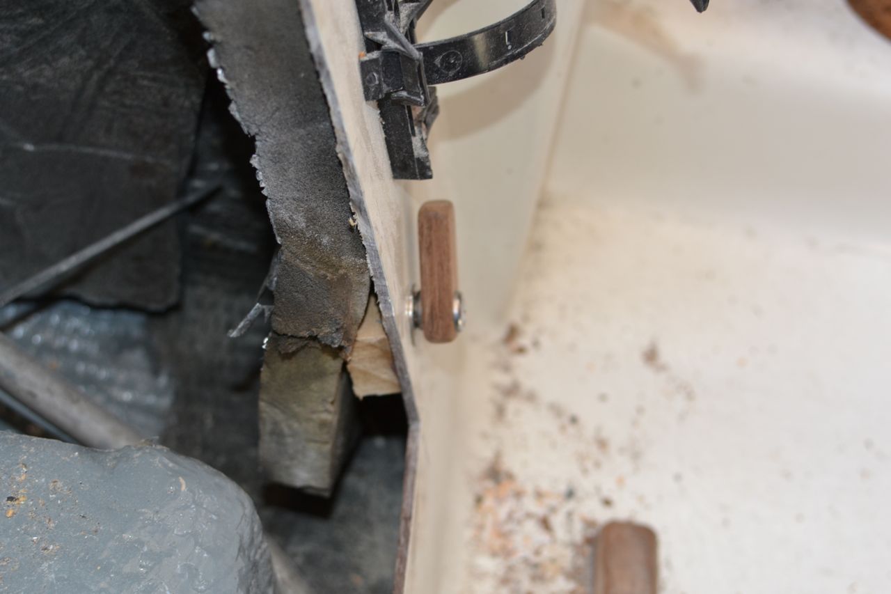
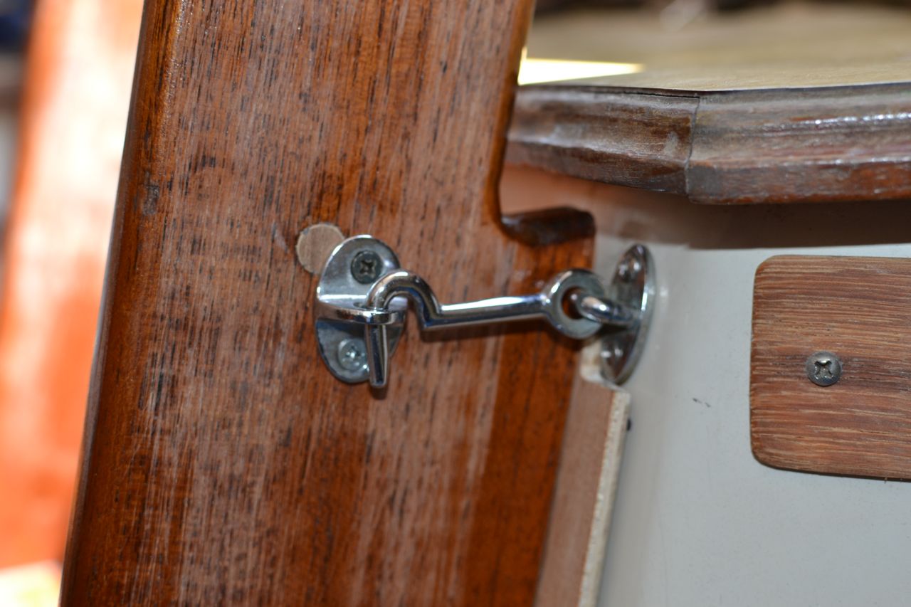
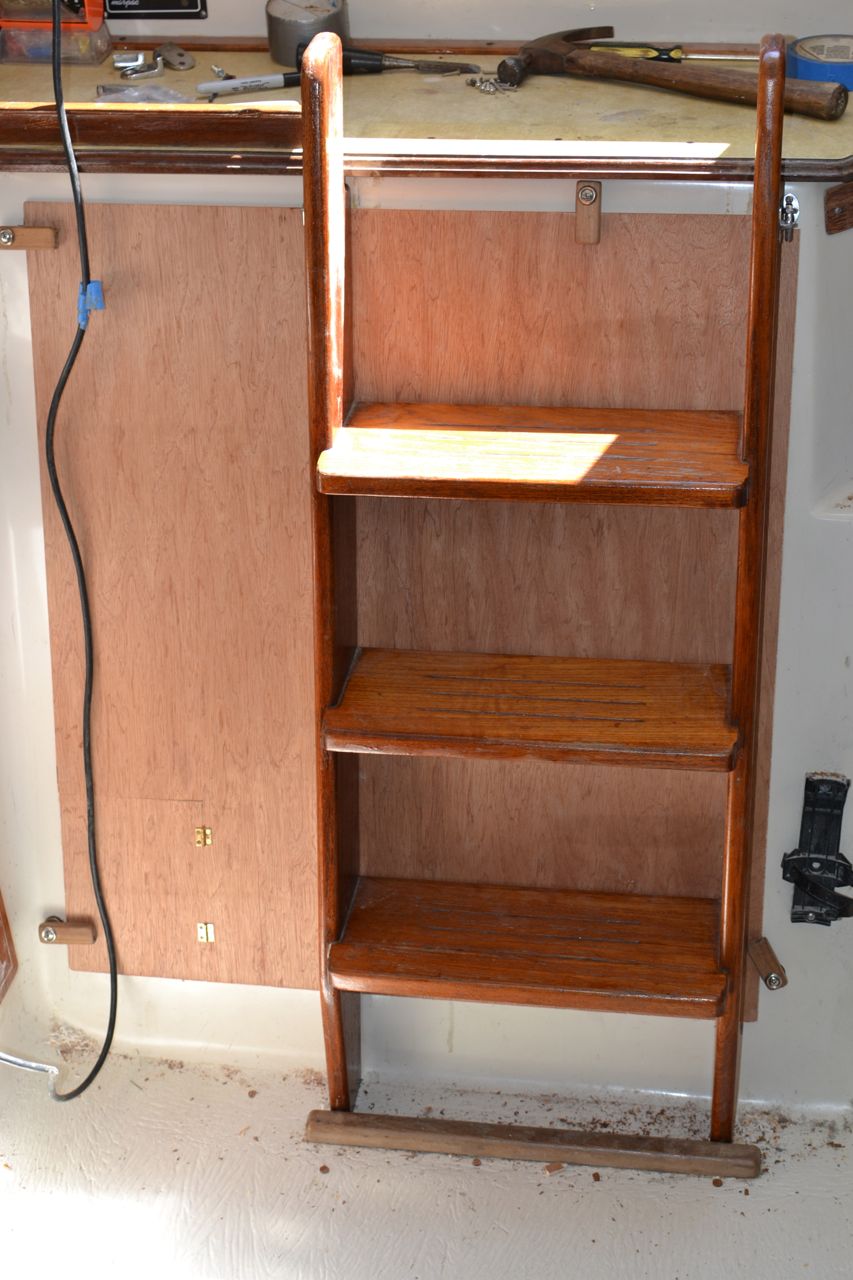
I had a lot of time for this project today, and finished the construction phase. Actually, with some time spent over the last several days, I managed to design and install the turn buttons, and locate and install the ladder hardware. Here is a photo – which doesn’t really do justice to the amount of time that went into the these two little accomplishments:
You will have to click and enlarge
in order to see the turn buttons
on the corners and the hooks
mounted just under the counter top.
I ended up using some hook-and-eye hardware that my boat neighbor gave me as it was more heavy-duty and of “marine” grade. I mostly used it because of the heavier gauge material of its construction. The turn buttons were made of some teak decking scrap left over from another project. It took a bit of fiddling to get the spacers right between the facing surround and the turn buttons. Without the spacers, the buttons wouldn’t ride up onto the compartment cover.
Hook attached to a pad-eye.
Spacer between facing surround and turn button.
The next step was to install the eyes to secure the ladder, but first I had to fix the holes through which the clevis pins were passed in the old system. Here are a few photos of the holes being bunged and hardware installed.
There were four bungs like this because the plugs
weren’t long enough to fill the two holes front-to-back.
The bung is trimmed and sanded flush,
and the eye installed on the ladder.
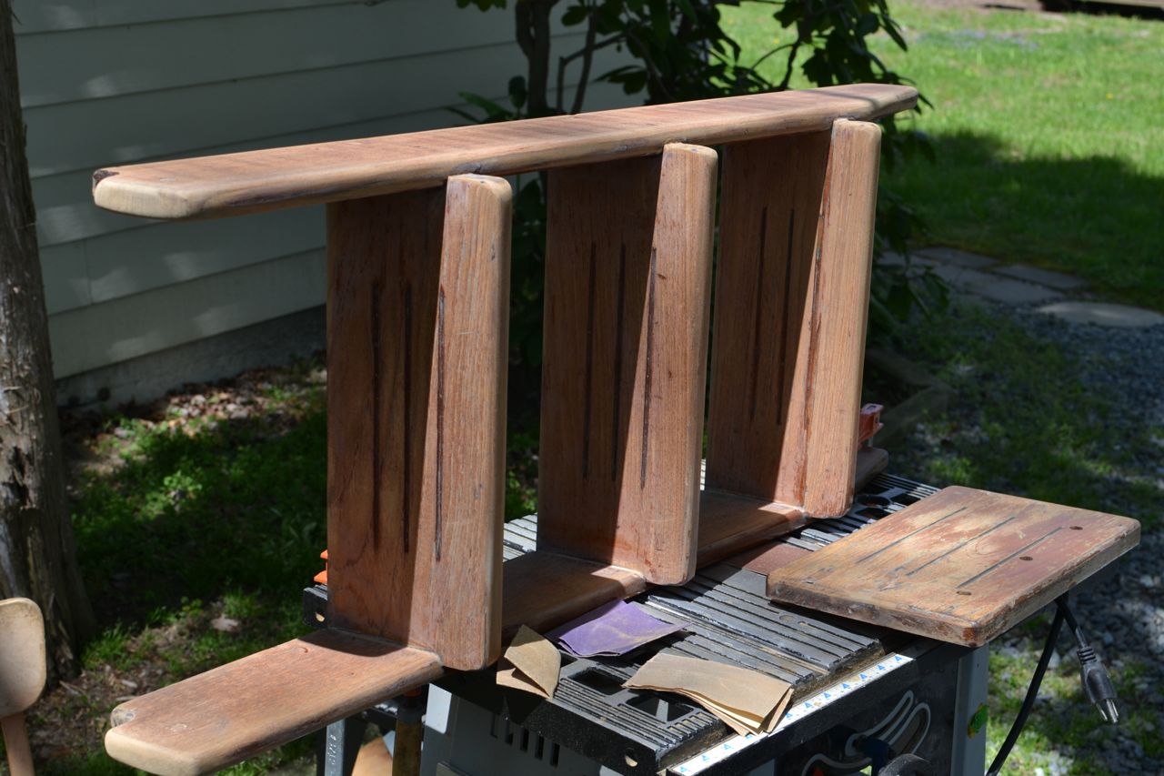
With the holes bunged and the hardware located on the ladder, it was time to refinish it. I sanded it all smooth and removed all the old varnish. I also trimmed the top of the ladder uprights even with the counter top. Having them extend above the level of the counter looked like a trip hazard to me.
Ladder trimmed and sanded smooth.
I trimmed about four inches off the top of each upright.
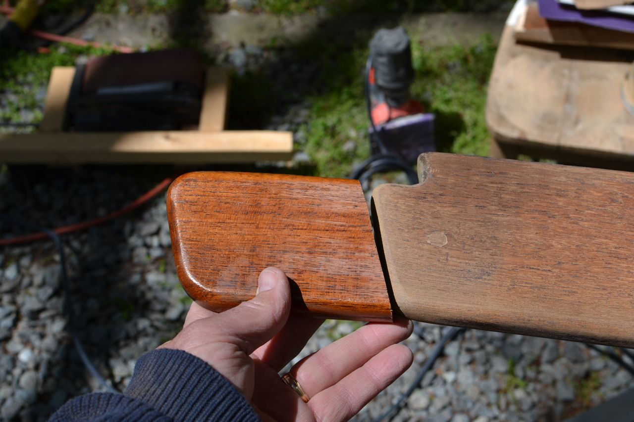
I also repaired the top step that was mounted on the counter top. The wood split out when I removed the old bungs. I repaired it with epoxy, bunged the old mounting holes, and sanded it smooth.
Bunged.
Repaired and bunged.
Clean and ready for varnish (sorry about the shadows).
Compartment cover and ladder in place.
This is before trimming the ladder tops.
I spent the rest of the afternoon sanding and varnishing with a sealer coat. I also sanded and sealed the teak trim around the counter top. It was in terrible shape and has bothered me for years. This is finally the right time to clean it up.


Tuesday, June 11, 2013
New Engine Compartment Cover
Over on s/v Cay of Sea, Rick has been busy constructing a new engine room cover. Today we see how he constructed it (and thanks for the shout-out Rick!). This is Part I of a two-part series - watch for Part II later.
The old engine compartment cover doesn’t fit since I enlarged the compartment access. Motoring across the creek from the boat yard underscored for me how important it is to have that hole covered up, preferably with a cover that would absorb engine noise. My goal for the engine compartment cover was just this – fill the hole, muffle the noise.
First, a photo of the old cover for reference:
Nothing special, really. The 1-inch mylar-backed
foam insulation that covers the back of it is in
bad shape. I was never happy with how the edges
sealed the air space, and the door was difficult
to get my hand through.The old cover fit okay, but was never flush to the outside of the compartment. So there was open air space around the edges, which let out more sound. Even when I installed weather-stripping, I couldn’t get it to close all the way. Reaching through the door to operate the raw water seacock was uncomfortable, etc., etc. I wanted to make a new cover that didn’t have these little annoyances.
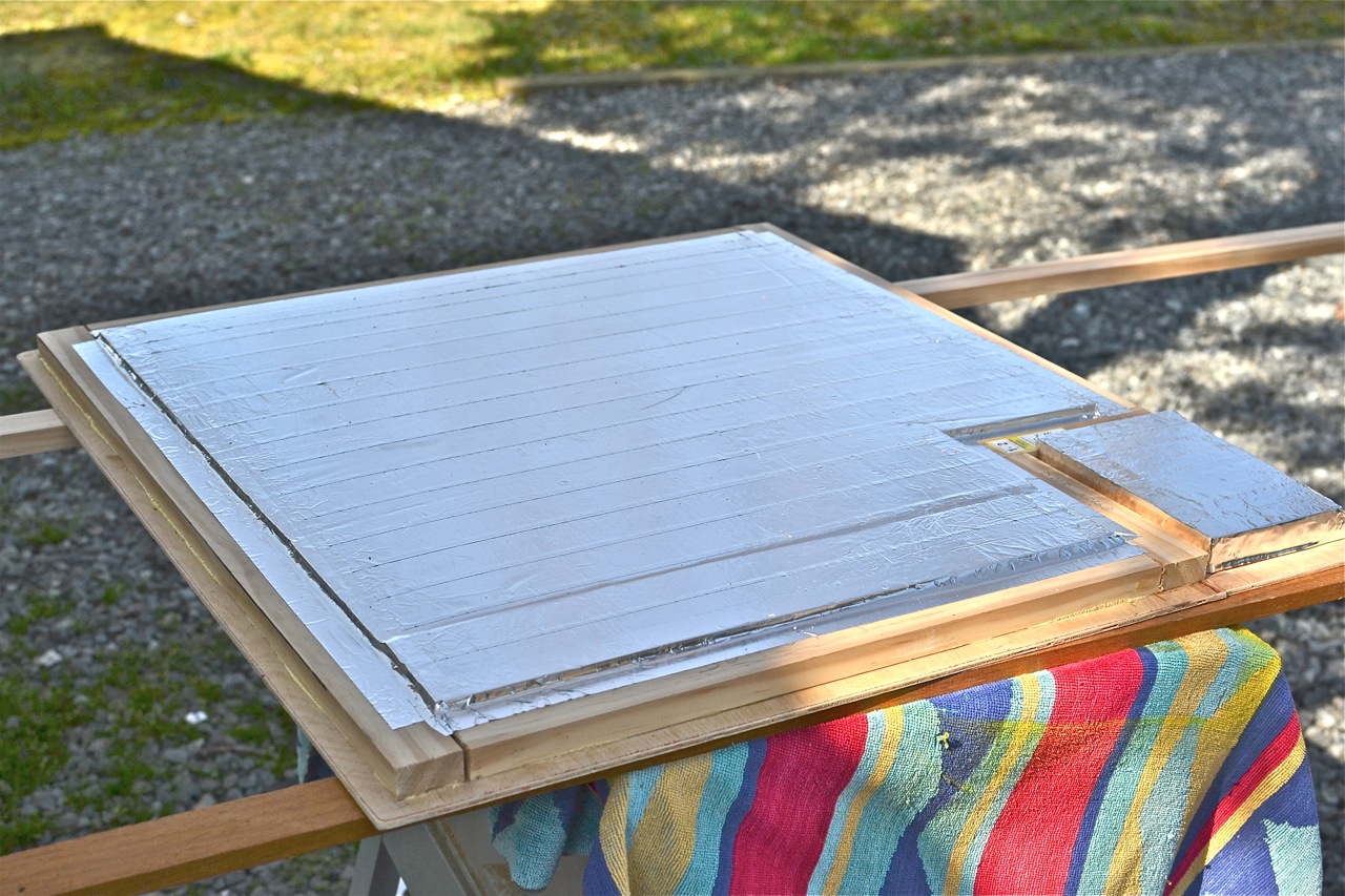
I began with a 4′x4′ piece of “underlayment,” which is just a piece of 1/4″ ply with one good side. The grain is fairly even, and its color is closer to mahogany than birch ply, which starts out a lot lighter in color. We have a 4-door sedan (Nissan), and it was a bit of a puzzle to get it into the car for transport. Wish I owned a small pickup . . . I also bought some 1″x2″ for framing out the panel, two 2′x2′ squares of pink foam board for insulation, two rolls of aluminum tape, a tube of construction grade exterior adhesive (like Liquid Nails), and two small brass hinges w/fasteners.
I carefully measured the opening, and cut the plywood to exceed the dimensions of the hole by 5/8″ all around. Then I carefully measured the panel and marked it for the framing– too big! I made it exactly 5/8″ smaller than the outside dimensions of the ply, and my test fit (of course) revealed that the inside frame was exactly the same size as the opening – duh. I knew there was something wrong with that when I did it. Fortunately, I just had to remove an 1/8 inch more material in the engine surround, and the panel fit perfectly. It took 10 extra minutes, and I was back on track.
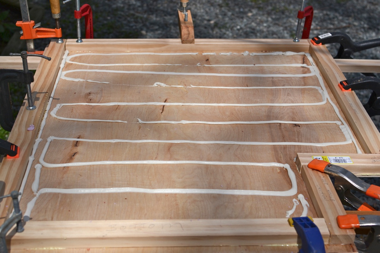
I cut the pink foam board to fit inside the frame, and applied the construction adhesive.
I used the entire tube. No reason not to.
The frame is glued only – no screws.
I almost had enough clamps!
Foam set into the adhesive.
You can see the door cut-out, which was foamed separately.I set moderately heavy things on top of the foam, and went inside for lunch, waiting for the adhesive to cure.
Of course, the first time I laid in the foam,
I put it wrong side down. It cleaned up easily. . .
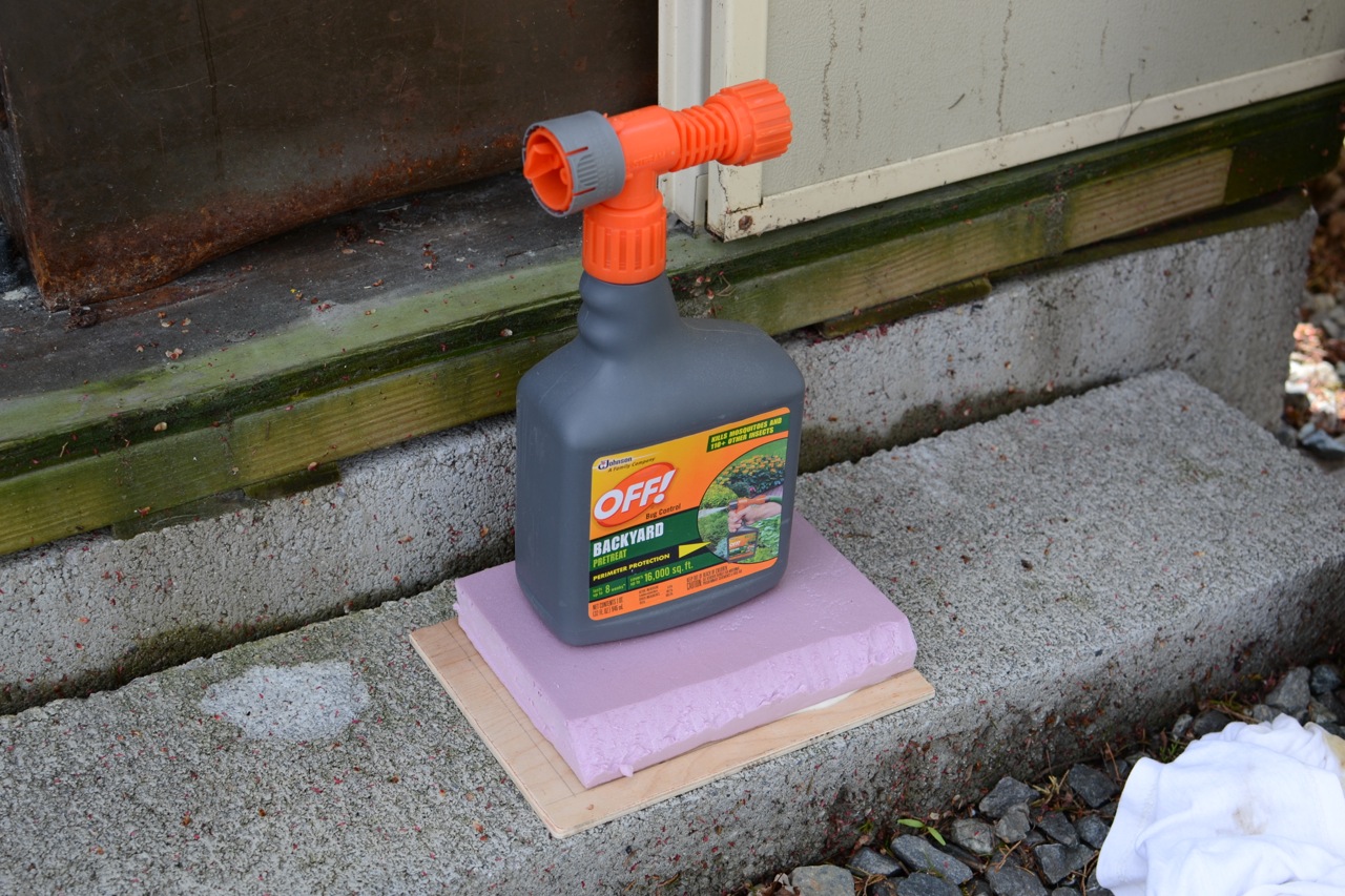
Moderately heavy things pressing the foam
into the adhesive.
This is the door section with its own modestly
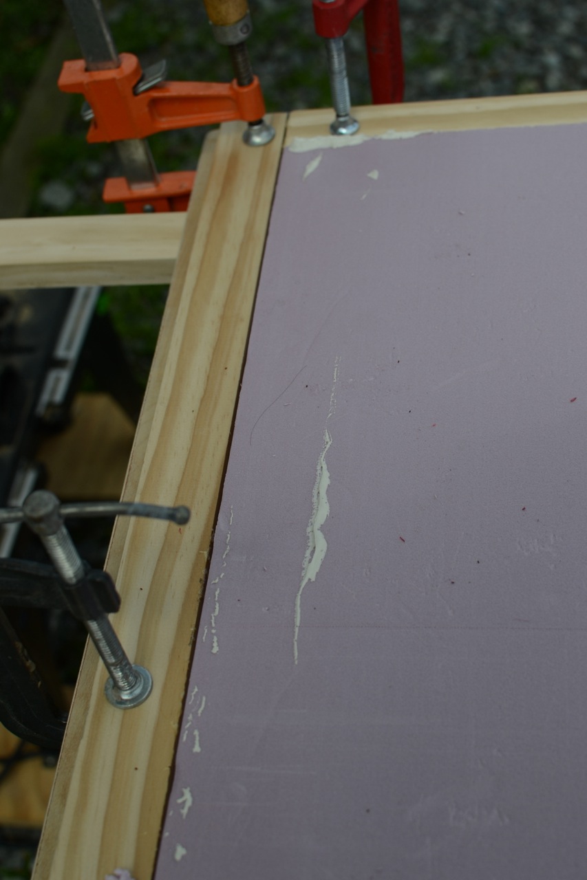
heavy thing pressing the foam down.After lunch, I taped the entire surface of the foam with aluminum tape. I need to pause here, and acknowledge Robert Salnick for the information about this stuff – it is a great product. He featured it on his blog not long ago, and I was taken with the idea of applying a metallic surface to an otherwise non-metallic material. This foam was the perfect place for it. The tape adds density (sound deadening), moisture resistance, and fire resistance. And the sticky back is very sticky. I taped all the foam surfaces with it, and taped down the perimeter to the inner frame.
In progress. The tape has a peel-off backing,
and comes in rolls of 30 feet.
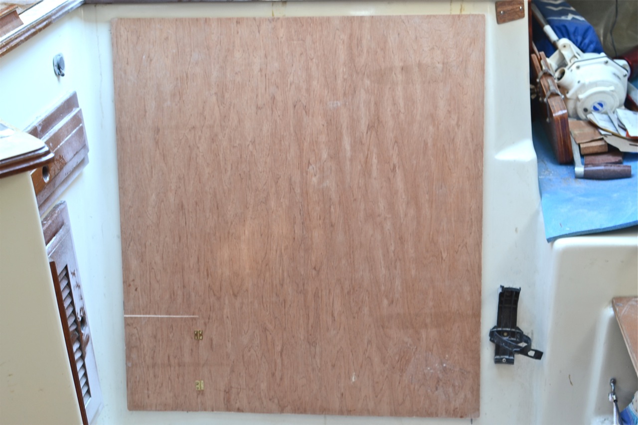
The old cover featured a frame around the perimeter with mitered corners. I left the frame off the new cover. I didn’t see that it added anything substantive. I saw a photo of my friend’s Watkins 27 (thanks again, Jim Brewer) who had omitted the frame from his. I thought it looked clean and simple, and I adopted the idea. After installing the tiny hinges and seacock access door, I took it down to the boat for a fit. Here are a couple of photos:
I may fashion a turn-button to keep the door closed tightly.
Three coats of varnish will darken the material
and make it blend with the rest of the
interior woodwork.There are a few more items to finish. I will secure this cover at the corners with screws. Like the original cover, this one doesn’t lie flush and tight against the surround either. A screw in each corner will pull it down tightly. I’ll install weather-stripping for a gasket all around. I also need to reinstall the top teak tread/step directly to the counter, trim the top of the ladder, and refashion how it secures to the counter. Then all of it gets new varnish to look fresh.


Wednesday, May 29, 2013
Fischer Panda Cooling System Modification
Do you have a Fischer Panda generator? Depending on its age, the following improvement by Paul of s/v Solace will be verrry interesting to you...
Fischer Panda (FP) Generators are now cooled by fresh water and the sea water only passes through the heat exchanger and then out via the exhaust hose. BUT it didn't use to be that way. My FP is around a 2001 model, 5.5KVA. In my FP the cooling is done with sea water, which first goes around the generator casing and then to the heat exchanger, before exiting via the usual exhaust method. The fresh water gets circulated around the engine and through the heat exchanger to get cooled from the seawater that has picked up a little heat from the generator casing.
You can see the heat exchanger situated underneath the generator in the picture below. I consider that poor design and changed my heat exchanger location which you can read about here and also here
To change my cooling system, I figured it was only a case of changing a few hoses over and I could have both my generator casing AND my engine cooled by fresh water and use the raw water only for cooling through the heat exchanger. Read below how I did it...
FP blurb about their water cooling.
First I removed the freshwater hose that went from the engine to the heat exchanger. You can see the fresh water hose coming from the pump (above generator belt) to a metal tube which then does a small bend and goes down and sits just behind the Johnson raw water pump. The removed hose is sitting in front of the pulley.
Next I removed the hose from the raw water pump which goes straight down to a pipe that dives under the motor to the generator casing.
The idea is to swap these two over. Fresh water will now go to the generator casing, and raw water to the heat exchanger.
In the picture to the right, you will now notice, the pipe that sat under the raw water pump has been moved to the right a little and hooked up with the fresh water pipe coming down from the fresh water pump. (pump not seen). I had to cut about two inches (50mm) off the pipe so that a hose will connect.
I had this 20mm pipe (in picture to the left) made for this change over.
In the picture to the right, you can just make out the curved pipe as it is now attached to the raw water pump and the pipe continues to the heat exchanger underneath the pulley.
Now, at the heat exchanger. the pipe that use to be fresh water is now raw water and should be connected to the raw water input at the heat exchanger.... AND the raw water input hose at the heat exchanger is now fresh water. Just swap the two over.
So, lets follow the path of the fresh water first.
From the fresh water pump, it goes down beside the crank pulley and dives under the motor to the generator casing. From the generator casing, the fresh water goes to the heat exchanger to be cooled and then returned to the engine at the header tank. From the header tank, it gets circulated around the engine and repeats the cycle.
Now the raw water.... It leaves the raw water pump and goes straight to the heat exchanger; picks up the heat and then exits via the exhaust. Just like the new FP's.
Finale hookup with generator belt back on.
BUT, that's not the end of it. You might imagine that the generator casing may have some internal salt deposits. So, I first ran the engine up with fresh water to temperature and then after cooling down some, drained that water away. I then did another run up using a product called "Salt-X". I mixed with water as per directions and repeated the draining of the fluid after cooling down some. This Salt-X is a produce for removing salt deposits in outboard engines and should be available in most marine Chandler stores. Finally, I did another fresh water run up and emptied that too, before using a ethylene glycol "antifreeze/antiboil" product. I'll change that in about 9 months time as well; to make sure all salts that remained have left the cooling system.
We also have a fresh water flush system for both our engine and Genset. As we get ready to shut them down for a while, we open a valve to our fresh water tank and close the sea cock. We let the engine run for a minute or two and this then flushes out the seawater from the heat exchanger. Thus prolonging the life of the heat exchanger. Then, after shuting down the motor, it is important to close that fresh water valve; otherwise, the next time you open the sea cock, it can back pressure to the fresh water and ruin your tank supply. It usually only happens once. :-D
All up, it took about 2 hours and a ten dollar item to complete. Antifreeze and Salt-X were extra costs; but you should replace you antifreeze once a year anyway. It's mostly for the anti corrosion properties that we use it.The engine actually runs slightly cooler, and with a trip up to the tropics soon, will be beneficial.


Thursday, April 25, 2013
Don’t drop that nut!
Over on s/v Zero to Cruising, Mike has a new take on an old mechanic's trick - how to keep a fastener attached (temporarily!) to a tool for one-handed use...
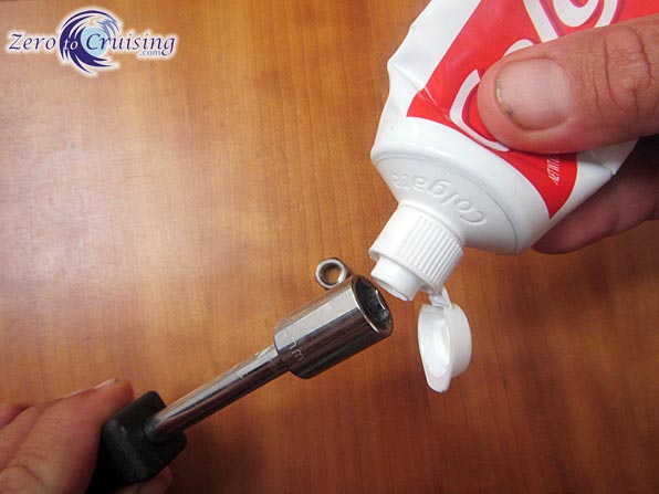
Yesterday we had plans to make a quick run in to Basseterre, the main city here, to stock up on groceries. Alas, quick was not meant to be. When I went to fire up the engines prior to raising anchor, I found that our port engine was on vacation. Sigh. A fair amount of troubleshooting went on following that discovery. Perhaps I’ll write about that later. What I will say is that, at one point, I removed the carburetor and the most difficult part of that job was trying to get the two main nuts back onto the bolts when I went to reinstall it. I really didn’t want to drop the nuts in the water. Seriously!
4-stroke carbs are definitely more complicated
than 2-stroke carbs!
After a few tense moments fiddling with the nuts, trying to squeeze my fingers into a space too small for them to fit, I remembered a tip that our friend Kirk shared with me, illustrated in the following pics. Of course, when he described the trick, he suggested using grease. As I didn’t have any immediately handy yesterday, I improvised with toothpaste. Guess what? It worked perfectly! I would recommend that, if you decide to use toothpaste too, you wash all of it off your tools and parts when you’re done. I have no idea what the long term effect of toothpaste is on metals.


Subscribe to:
Posts (Atom)


