We have added two new 1-1/2” thru-hulls above the water line. The port thru-hull will serve as the discharge for the upper, larger capacity bilge pump (3700 G/H).
The starboard side thru hull will act as a drain for the deck scupper. We did not like the long hose run from the starboard scupper to the torpedo tube drain manifold. We also wanted to rig a method for collecting water off the deck if necessary.
Prior to drilling any holes we assembled the new starboard deck drain plumbing.
Test fit of new plumbing for starboard deck drain. Note old drain hose at far right. Test fitting the new plumbing allowed us to accurately mark the location for the starboard thru hull. The port side fitting connects to a single flexible hose so identifying the exact location was less critical.
Since the location of the holes was marked on the inside of the hull, I began the drilling using a ¼” bit to drill a pilot hole from the inside out. The ¼” hole matches the diameter of the hole saw pilot bit. Next, I chucked a 1-7/8” hole saw into the drill and moved outside the hull. Drilling the larger hole from outside allows for properly aligning the hole perpendicular to the hull and creates less dust inside the boat.
We drilled two 1-7/8" holes in the hull. The Morgan 382, 383, & 384 hull’s have a foam core above the waterline. This is the first time we have drilled large diameter holes above the waterline and subsequently our first look at the coring material.
Close up of plug offers a glimpse of Morgan's construction techniques. The hull is slightly over one inch thick… the outer fiberglass layer is 5/16”; the foam 9/16”; and the inner fiberglass layer 1/8”Placing holes in cored hull’s or decks requires additional effort to ensure water never reaches the core material. In smaller, fastener sized, holes this can be achieved by over drilling the size of the hole and then filling it back with epoxy. Larger holes for plumbing fixtures require a different approach.
Using a small flat screw driver and a couple different styles of picks, we removed all the coring material within approximately ½” of the hole.
Foam core removed from the area around the hole. The plan is to fill the newly created void around the hole with thickened epoxy. So the next couple steps are the usual epoxy prep… 80 grit sanding, acetone wipe down, mask area... We used a syringe to apply the epoxy and a plastic spreader to achieve a nice clean finish.
Filling the area around the hole with thickened epoxy. After a couple days for the epoxy to fully cure, we returned to the project. Using a #49 cabinet rasp and some 80 grit sand paper, Anne cleaned up any excess epoxy from the holes. While I cut down the length of the threaded section of the thru-hull to properly fit the valve on the starboard side.
Prior to applying any sealant we dry fit the two thru-hulls and masked the surrounding area. For the final install we used 3M 5200 sealant. Anne worked the interior and I the exterior.
New thru hull fittings are just above the waterline and five feet forward of the torpedo tube drain on either side of the hull. We are still waiting on hose to connect the bilge pump to the new fitting on port, but we wasted no time installing the new starboard deck drain plumbing.
New deck drain w/ option for filling water jugs installed. Since the installation we have weathered a couple heavy rains. The starboard deck scupper is performing much better with the new system.
What was that you said?
Why yes that is a new battery selector and bilge pump switch panel in the image above. I’ll post more info on that project very soon.
Showing posts with label plumbing. Show all posts
Showing posts with label plumbing. Show all posts
Tuesday, October 13, 2015
How To Make Holes In Your Boat
Making a hole in your hull is serious business, even more so if your hull is foam-cored. Jeff and Anne aboard s/v Pilgrim and in the midst of a complete refit demonstrate how it should be done...


Thursday, January 29, 2015
Dry Bilge
Mike and Rebecca on s/v One Love really want a dry bilge. And air conditioning a boat in the tropics was working against that goal. I am also an advocate of the incremental test/installation process that Mike used. Here's what he did:
Remember my post about wanting to have a dry bilge? Well, we ultimately decided to go the route of installing a couple of sump boxes to deal with the air-conditioners’ condensation. We selected this one[Tho not clean enough to drink, the condensate from the air conditioner would be an ideal source of ion-free water for battery maintenance. -Ed]and Michael brought two of them with him when he arrived on the 15th.
I am 80% of the way through installing the first of the two. Here are the steps I have taken thus far:
The next step is to permanently connect the outlet hose. My plan is to T it into the sink drain hose. In order to do that properly, I’ll need to place a non-return valve (check valve) in the outlet hose, just before the T. This will prevent any water draining out of the sink from finding its way into the sump box’s outlet hose*. Unfortunately, the chandlery will not have the check valve I need until some time tomorrow. Until then, we’ll be living with a hose zip tied to our sink.
- Before getting started, we dried and cleaned the bilges.
- I then ran a line from the AC unit’s drip tray outlet down into the bilge to see if it would gravity feed the water where I wanted it to. I put a short length of hose into a plastic container. We ran the air conditioner and it fed the water as I had hoped. I was surprised at how quickly it filled the container!
- Before doing any actual plumbing and electrical connections, I wanted to test the unit to ensure that it worked, and also to ensure that it would pump the water high enough to exit where I planned to dispose of it. We tested this by taking the sump box out into the cockpit, connecting a hose to the outlet and filling the box with water. While Rebecca held the hose in the air, I applied temporary power to the pump using a 12V plug and alligator clips. It worked as we had hoped.
- The next step was to attach the inlet and outlet hoses. We had already made one trip to the chandlery to purchase parts for this (hose, clamps, fittings). This particular box has multiple inlets of various sizes. The strange thing (to me) is that you need to saw off the end of the inlet that you want to use! It seems to me there could be a better solution but it is what it is, I cut it off.
- I temporarily positioned the box in the bilge, a location which is at a lower level than the AC unit. This allows the condensation water to gravity feed into the box, as tested earlier. I connected the sump pump’s power leads to a bus bar in a nearby junction box which supplies 12V to the electric bilge pumps. The outlet hose I simply ran into a nearby sink. We tested the operation of the unit in this configuration and it worked perfectly. The AC unit ran for some time and the bilge remained dry as we had hoped.
*Alternatively, I guess I could route the sump box outlet hose so that it feeds down into the drain hose. Gravity should then prevent the sink water from making its way into that hose.
Notes: I also want to plumb our refrigerator’s drain into this sump box. The sump box that I’ll be installing on the starboard side will have to deal with the condensation from both the salon AC unit, and the starboard hull’s AC unit.


Thursday, January 8, 2015
A Magnetic Personality
This post originally appeared on Windborne in Puget Sound
Like the rest of the country, the Pacific Northwest has been experiencing unseasonably cold temperatures of late (well, ok - for us, 32° is unseasonable). And of course you know what this means... our heating system failed. Just like roof leaks only appear when it rains, heating plants never fail in the summer. Oh well.
The first clue was that the thermostat display was completely blank. Well, and the boat was cold, too. Some back and forth with Marinaire, the heat pump manufacturer (great customer service, by the way), disclosed that there was a fuse on the main circuit board - a fuse hidden beneath a blue vinyl cover. Yep, it was blown. When it was replaced, the replacement blew immediately as the fan and circulation pump tried to start. Blowing a couple more fuses revealed that the problem was the circulating pump - the pump that provides sea water to the heat pump. (It is by the chilling of this sea water that the heat pump produces heat.)
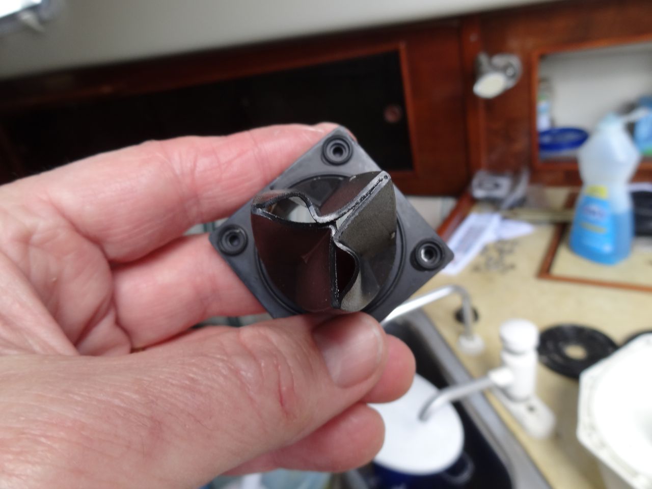
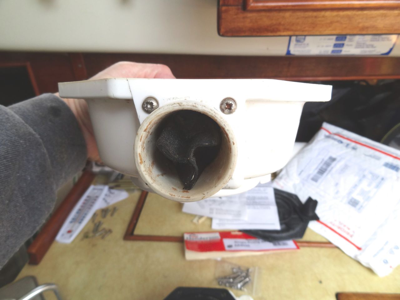
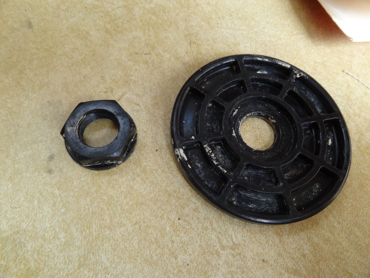
Here's the pump after I pulled it out:
Yup - the shaft seal failed and sea water was trickling back along the shaft and into the electric motor. Bzzzt!
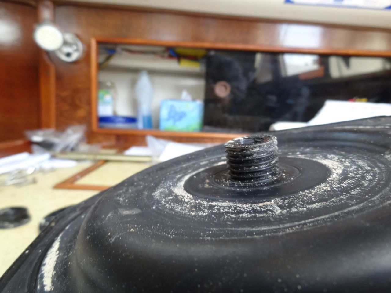
So I bit the bullet and ordered a new pump. This one has a magnetically driven impeller - that is, there is no shaft seal. The motor drives a cup-shaped magnet; the pump body extends into the cup but has no opening. The impeller has an imbedded magnet, and is thus driven by the motor without any mechanical coupling and without a shaft seal. As you might expect, this kind of pump is more expensive. But the technology is worth it.

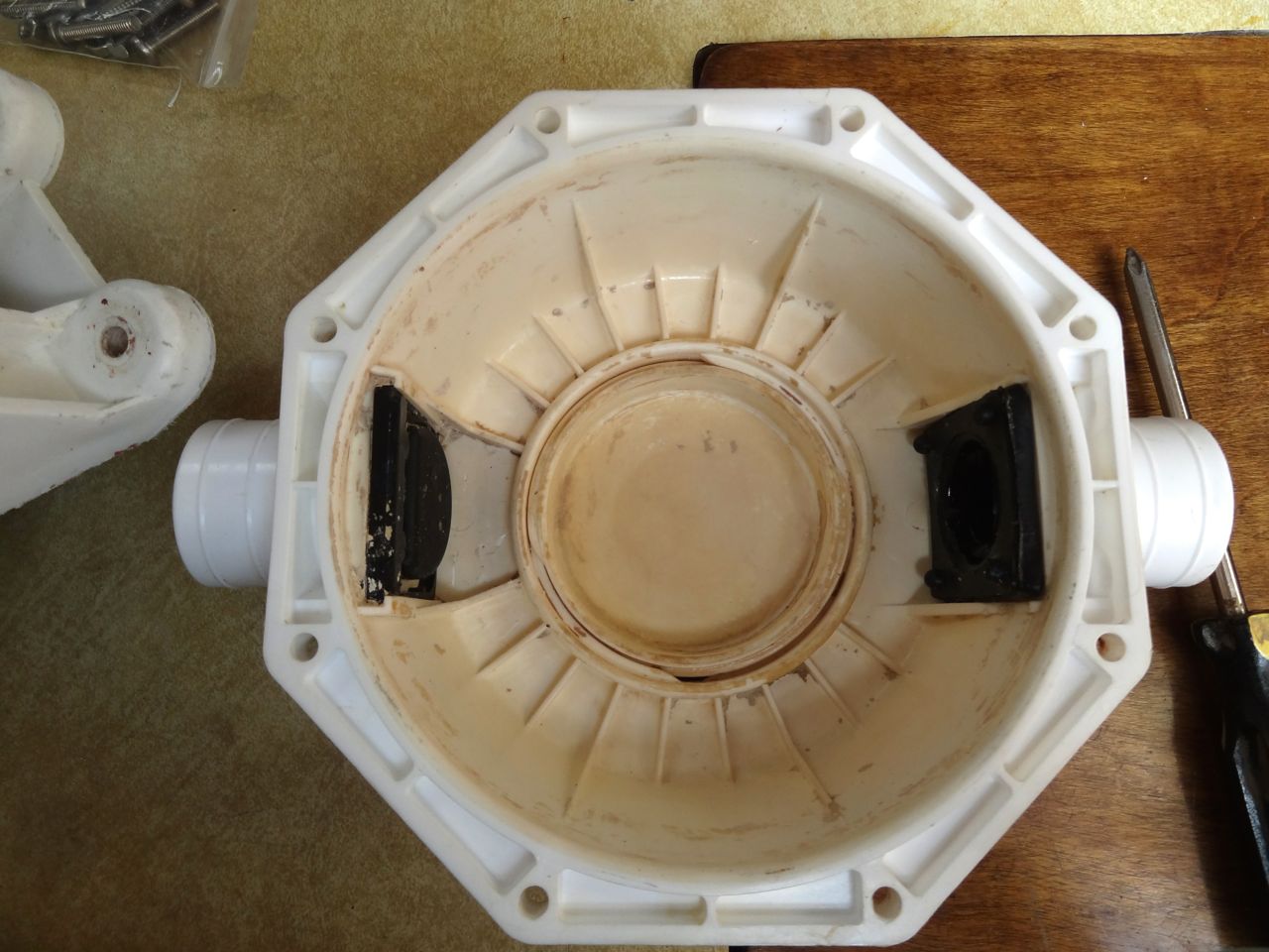
As a bonus, the pump body itself (the white plastic portion) is considerably larger than in the old pump, and is much more substantially made. The inlet and outlet are larger as well.

Since the pump is physically larger, it wouldn't fit where the old one had been. So there was some fooling around involved in finding a location that...
Based on the appearance of the discharge water stream, I'd estimate that this pump is delivering twice as much water as the old one, even tho both are rated at 500 GPH.
The boat is warm! And now I expect to be able to forget about this pump for a long while, just as I have been able to with the refrigeration circulating pump.
Magnetic personality? I must have one. Can I make a recommendation here? Avoid sea water pumps that have shaft seals wherever possible. Like the cosmetic ad says, they're more expensive, but you're worth it.
Like the rest of the country, the Pacific Northwest has been experiencing unseasonably cold temperatures of late (well, ok - for us, 32° is unseasonable). And of course you know what this means... our heating system failed. Just like roof leaks only appear when it rains, heating plants never fail in the summer. Oh well.
The first clue was that the thermostat display was completely blank. Well, and the boat was cold, too. Some back and forth with Marinaire, the heat pump manufacturer (great customer service, by the way), disclosed that there was a fuse on the main circuit board - a fuse hidden beneath a blue vinyl cover. Yep, it was blown. When it was replaced, the replacement blew immediately as the fan and circulation pump tried to start. Blowing a couple more fuses revealed that the problem was the circulating pump - the pump that provides sea water to the heat pump. (It is by the chilling of this sea water that the heat pump produces heat.)
Here's the pump after I pulled it out:
 |
| Salt water short-out |
So I bit the bullet and ordered a new pump. This one has a magnetically driven impeller - that is, there is no shaft seal. The motor drives a cup-shaped magnet; the pump body extends into the cup but has no opening. The impeller has an imbedded magnet, and is thus driven by the motor without any mechanical coupling and without a shaft seal. As you might expect, this kind of pump is more expensive. But the technology is worth it.

As a bonus, the pump body itself (the white plastic portion) is considerably larger than in the old pump, and is much more substantially made. The inlet and outlet are larger as well.

Since the pump is physically larger, it wouldn't fit where the old one had been. So there was some fooling around involved in finding a location that...
- was below the water line as far as possible - centrifugal pumps are not self-priming,
- was not actually on the floor of the bilge compartment, since that would promote rusting of the motor base,
- did not interfere with access to the nearby battery,
- minimized the required plumbing changes,
- and finally, did not block the access door you see in the background to the right.
Based on the appearance of the discharge water stream, I'd estimate that this pump is delivering twice as much water as the old one, even tho both are rated at 500 GPH.
The boat is warm! And now I expect to be able to forget about this pump for a long while, just as I have been able to with the refrigeration circulating pump.
Magnetic personality? I must have one. Can I make a recommendation here? Avoid sea water pumps that have shaft seals wherever possible. Like the cosmetic ad says, they're more expensive, but you're worth it.
Thursday, September 25, 2014
New Deck & Bilge Pump Drain Manifold
What Jeff and Anne have been doing to s/v Pilgrim is not a re-fit, but for all intents and purposes a complete rebuild of the yacht. Much of their work is too big to include in this blog, but some portions are self-contained and fit well with our format. This is one of them...
The Ted Brewer designed Morgan 382, 383, & 384 series has a unique, and I believe very well designed, system of deck & cockpit drains. A 4“diameter tube with exits above the water line transverses the beam under the cockpit sole. From the exterior of the boat it is possible to look through the tube and out the other side. Morgan owners refer to this drain as the “torpedo tube“.
Two, 2” id cockpit drains feed vertically directly into the tube. Port and starboard deck scuppers feed into the tube via a manifold located in the engine compartment. Pilgrim’s manifold was a tired, poorly constructed mess that grew new limbs to address additional plumbing needs.
Pilgrim's dubious drain manifold
A single strategic hack saw cut excised the manifold.
All the remains is the 2" id tube that feeds directly into the "torpedo tube".
Armed with a sketch of my vision for a new manifold, I headed into the hardware store. Amazingly the Beaufort Ace Hardware had everything I needed to fabricate the new manifold.
Dry fitting the new manifold.
The primary body of the manifold is 2” id schedule 40 PVC. The 1 ¼” id deck drain hoses attach at either end. The manifold also includes a ¾” id inlet for the small volume, primary bilge pump and a 1 ½” id inlet for the manual bilge pump.
To decrease the likelihood of down flooding and to maximize space in the engine compartment I elevated the new manifold 4” above the torpedo tube.
The new manifold is elevated 4" above the torpedo tube and supported to two eye straps
No bilge pumps are currently installed in Pilgrim – stay tuned - so temporary plugs are currently screwed into those inlets.
Bilge pump inlets are temporarily plugged.
We plan to reroute and replace the deck scupper hoses, but at present the existing deck scupper drain lines are feeding the new manifold.
Future projects will include replacing and rerouting the deck drain hoses.


Tuesday, September 2, 2014
Plumbing in the Right Direction
Over on s/v Cay of Sea, Rick tackles his head plumbing. He faces a problem that I completely understand - when Eolian's holding tank was plumbed at the factory, the connections to the inlet and the outlet were reversed, making the deck pump-out fitting completely useless...
In my last post, I confirmed the notion that fluids under pressure always obey the laws of physics. Fluids will flow towards the low pressure outlet every time – the path of least resistance, as it were. With this in mind and my back on the mend, I carefully boarded Cay of Sea today and set about to understand how I could have plumbed the overboard holding tank circuit in the wrong direction. Regardless of what I intended the plumbing design to do, it nevertheless obeyed the laws of physics perfectly and moved seawater into the holding tank, not out.
There were several possibilities as to why: 1) I had the Y-valve hooked up wrong; 2) I had the inlet and outlet hoses reversed; or 3) the opposite/but same effect – I had assembled the pump with the valves reversed.
It was number 3, actually. I dimly remembered from two years ago (as I was tracking down hoses and confirming their connections) telling myself that I had to reverse the assembly of the pump so it would pump 180 degrees from its current configuration. I didn’t do that when I reassembled it last week, so it very naturally drew water from the seacock which is intended to be the exhaust. I had the hoses off and the pump disassembled/reassembled in about 45 minutes.
By the way, a heat gun is the required tool for managing white sanitation hose. It simply is not possible to work with it any other way. When warmed up, it’s nice and pliable.
I also removed the vented loop from the holding tank exhaust. Yeah, that was an important move, seeing that its not possible to inject air at the top of the loop without creating a corresponding leak. However, not many people I know want this sort of leak in their boat. No, not at all. These loops, of course, are “necessary” for breaking any syphon that can flood the boat. I had suspected, but wasn’t sure, that this would allow “material” to leak out of the pathway to overboard. I was right, of course, because that’s the way they are supposed to work. However, it’s one of those details that “experts” fail to tell you as you read up on the subject. The “experts” emphasize the importance of having a vented loop in any line that is connected to an overboard fitting. I know, I know – you would think I could have worked that out for myself without being told. Well, I did eventually – and I learned this fact while pulling in seawater, not pumping out waste, so I feel thankful that I was spared that misery. Also, there is no risk of a syphon my case, because I close the overboard valves when the operation is complete. I will never leave that seacock in the open position.
You may also remember that I used flexible bilge pump hose for one of the tight bends in the circuit. I think that is going to work fine for two reasons: 1) I got the hose to seal on to the fittings with no problems, and 2) there will be no waste standing in this hose, as the pump has enough power to push all the fluid out of the hose. Besides, anytime I will use this pump-out option, it will include a clean seawater rinse of the system. Nothing objectionable will be left in the hose.
I reconnected the hoses with the pump reconfigured, and successfully evacuated the holding tank in about 3 minutes. Pumped in a little more seawater from the toilet, evacuated the tank again. All’s well. No leaks, no problems. Here’s a rough diagram detailing the overboard circuit:

Thursday, August 7, 2014
Freshwater Tank -- Are Bugs Swimming the Back Stroke in There?
One of the things that Drew at Sail Delmarva does is to design venting systems for large industrial tanks. When he talks about tank vents for boats, we should all listen:
According to the plumbing code and AYBC, there should be a screen on the freshwater tank vent to exclude mosquitoes, other bugs and reduce dust. But many builders, including PDQ, leave these off. On the PDQ 32 the vent line simply goes up and then down through a mushroom fitting under the bridge deck. Yup, I've seen bugs in there, so while I was up-grading my water system, I decide to fix this too.
Clean, huh? Though a strainer won't stop bacteria, it will reduce convective airflow.
The solution was to splice in a simple strainer. The code calls for 16 mesh, but no-see-ums are known to crawl through that, and 50 mesh is common anyway. This strainer is large enough to manage any air venting flow and serve as an over-flow too, though when filling fast, water will back out the fill even without the strainer in place.
Shurflo
The PDQ is a catamaran and the pressure water system is located on the bridge deck, between the hulls. Thus, the tank vent actually discharges down, through the floor, about 20 inches above the water line.
A 15 minute fix. No more bugs. Fewer bacteria and mold spores. Mostly self cleaning, every time I over fill the tank, but also easy to clean and easily accessed. I suppose I should clean the tank one last time, but the new filter is doing great.


Thursday, July 24, 2014
Another Pump Rebuild – Henderson Mk V Bilge/Diaphragm Pump
Rick on s/v Cay of Sea is on a pump rebuilding tear...
My service kit arrived today for this Henderson Mk V manual bilge pump, so I took some time this afternoon to rebuild it. This was the easiest rebuild of the four different type pumps that are on Cay of Sea.
The Henderson pump is actually destined for use as a holding tank evacuation pump. When we go off shore (eventually), I want to be able to empty the holding tank overboard. I discuss my refit of the sanitation system on board Cay of Sea here.
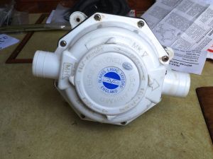
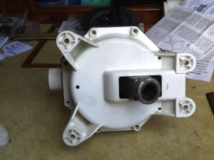
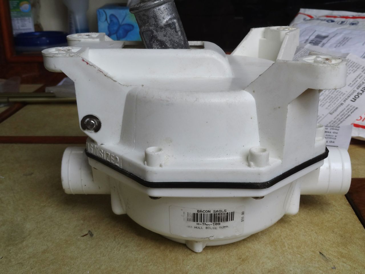
Above are images of the very large and bulky pump body. The bottom and top halves are fastened with 8 self-tapping screws, and the diaphragm also serves as a gasket between the halves. The casting and labeling seen above actually identify this pump as a “Blakes Lavac” pump, but it is a Henderson Mk V. It is supplied by Lavac (and labeled as made by them!) as their preferred pump for their vacuum-operated marine toilets.
There are only a few parts in the service kit: Two valves, an O-ring gasket, and the big rubber diaphragm are the heart of the kit. It also comes with new stainless fasteners and snap retainers for pivot shafts.
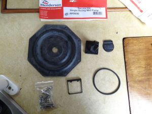
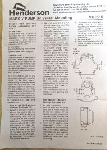
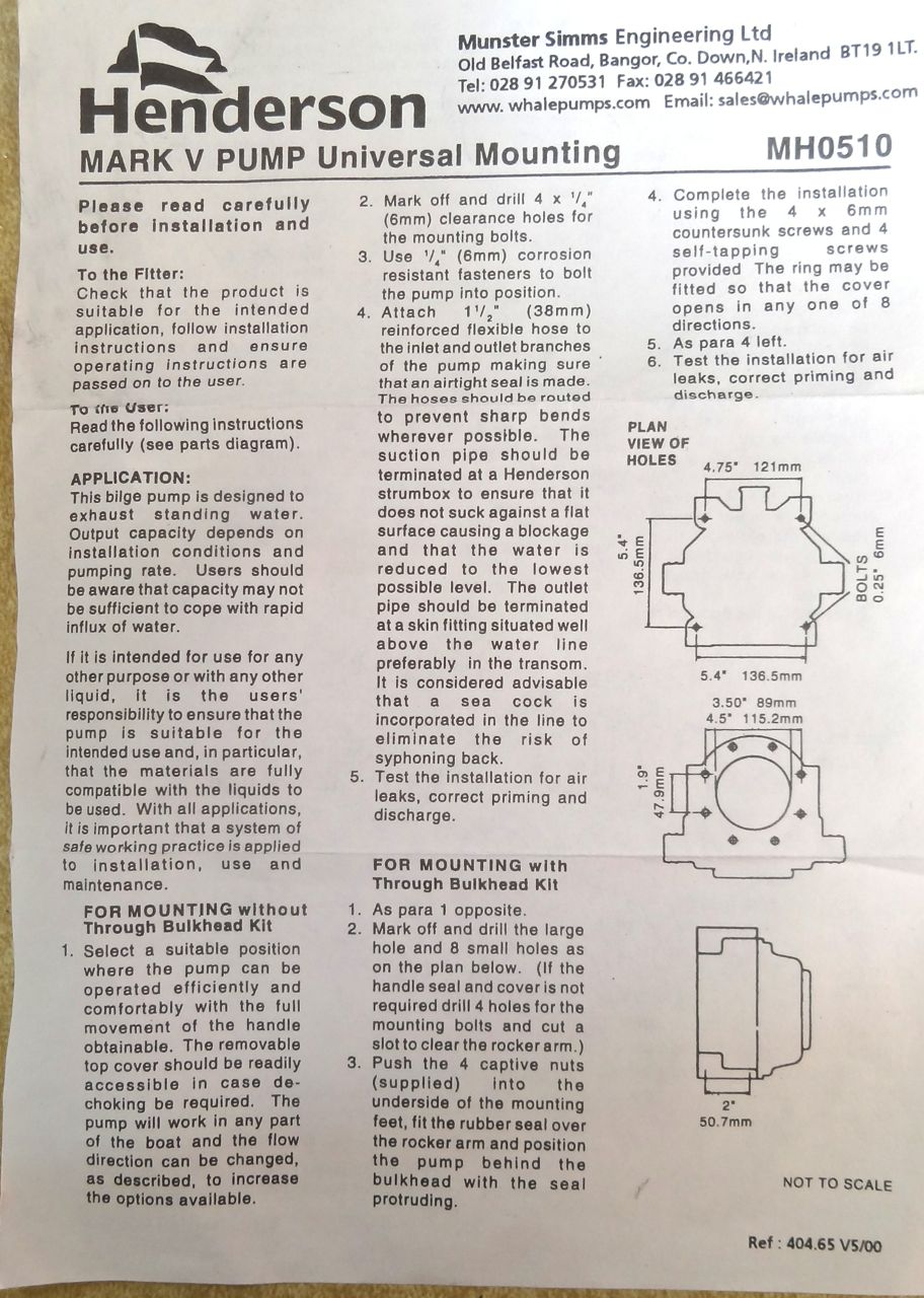
The instructions are useful, including a complete parts inventory reference, plus the various options and requirements for installation. I was a bit dismayed by one of the parts supplied: the “joker” valve, or back flow preventer, was distorted and looked to be in worse shape than the joker valve I was replacing. While the rubber of the new one was slightly more supple, the distortions in shape made me doubt that it would close properly when pulling a vacuum. I cleaned the old one, lubricated it with dish soap, and reinstalled it. The joker valve is held in place with four stainless screws. It’s easy to remove and replace.
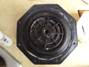

The diaphragm is moved by a lever which is attached to an actuator arm. The end of the arm is threaded to received a large diameter nylon nut. Two large plastic plates mount onto the actuator arm and are secured in place by the nut. Photos make this easier to understand than text.


I see now that I forgot to get a photo of the actuator arm without the diaphragm in place. Sorry, guess you’ll have to refer to the illustration (above) for that. I did not remove the actuator – there was no need to.
I also replaced the old flapper valve (think of a one-way door) with the new one from the kit.
I installed the new diaphragm, reassembled the pump halves, carefully tightened the screws all around as evenly as possible, and continuously checked the gasket contact area for fit and seal. After it was put back together, I checked the pump by inserting the handle into the socket and pumping it while checking for suction with my hand. It pulled well – unlike before. I’m not sure which component was the culprit – perhaps an accumulation of little leaks throughout – at any rate, it works now.
I’ll review its installation in the head in another post.


Tuesday, July 8, 2014
Rebuilding Whale V Vertical Lift Hand Pump
Aboard s/v Cay of Sea Rick continues his series detailing how to rebuild pumps; today it is a Whale hand pump:
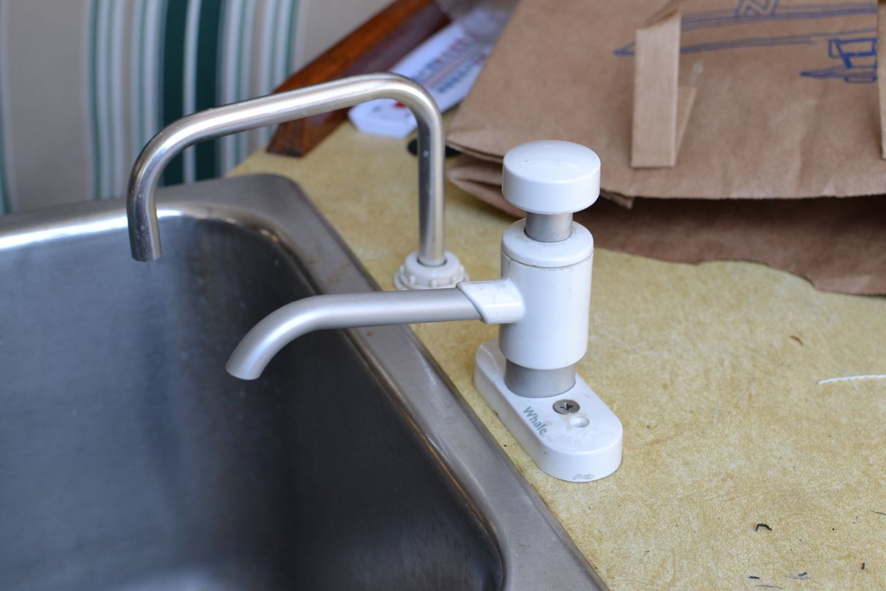
My second pump rebuild is the Whale V. I have two of these on board – one for the drinking water system, and one for the head lavatory. They both needed rebuilding, and I completed one yesterday. Here are the photos and discussion of that process.
This rebuild was a little less straight-forward than the tiptoe pump described in the previous post. There are a few more parts, and they are very much sequentially assembled. My inevitable errors – both in disassembly and reassembly – made the process a bit more time-consuming. It is important to keep track of which parts are removed and replaced. Several of the replacement parts look very similar, so comparing the removed part with the replacement is essential. Here is a link to the exploded view and service kit. This kit costs about $15.
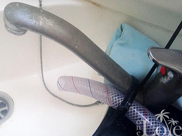
Unscrewing the hose fitting at the bottom of the pump provides access to the interior parts: piston, seals, o-ring gaskets, etc.
Although the instructions warn that the gasket inside the spout housing is the most difficult to replace (and recommended not doing unless absolutely necessary), I did not find that to be the case. I had to dig the old gasket out, which was slightly difficult. Then carefully compare parts to ensure I put the correct one back in place. More difficult by far was re-assembling the pump in the right order. I had to do it two or three times before I got the sequence right. It will be obvious if you get it wrong, because the piston will not go back in the cylinder if assembled out-of-order. There is a valve at the bottom of the piston that must be screwed on after the piston is back in the cylinder. It’s not complicated, really. Just takes a bit of trial-and-error.
The little gutter washers are the most problematic – these are circular rubber cups with channels in them, and there are several of them – slightly differently sized. They are easily unseated as the pump is reassembled, so you might feel like you need three hands at some point during the process. The whole process took about 30 minutes. I loosely seated the pump in its mounting location (see top photo), waiting to fasten it in place until I have re-plumbed the drinking water lines with new tubing. The hard water in our water source leaves deposits inside the lines after several years of use, then begins to flake off into the water. We filter all the water with a Brita pitcher, but the water doesn’t look very appetizing with little white floaty things drifting around in the top reservoir of the pitcher. Time to change out the lines. . .


Tuesday, June 17, 2014
Gettin' Heady with it!
John continues spiffing up his Catalina 30, s/v Dulcinea. Today, his project is a complete refurbishing of the head compartment. I think his changes made a great improvement - don't you?
I had a few goals to accomplish in the Head... or bathroom... replace the ugly counter top, Put in a new Faucet/shower, hide the ugly holding tank pump out and vent hoses, and brighten the head up a bit. In the process I wanted to move the sink slightly, as I always felt it looked awkward where it was.
The ugly Head... Some sort of non-functional kitchen sprayer for a faucet, no shower, weird teak things, and head hoses... After removing the counter top, The first step was cutting out a new one, by tracing the old one, and using my Jigsaw. Then I had to figure out where I wanted the sink to be, by placing a Template I had cut out of paper, an moving it around until I was happy with where it was. Next, cut the hole out, and take the counter to the boat for a dry fit, and to trace the new Sink location.
Now I had to cut out the fiberglass --- Crap! I left my Jigsaw at home! No matter, I have a Dremel on board... it wasn't pretty, and took 10 times longer, but I got the Job Done!
Finally! got it cut out!
Now it was time put the Formica on! If you have never worked with this stuff, let me tell you, it is challenging. It is fairly flexible, but will snap, after a certain point. Handling a full sheet of this by yourself without causing it to break is next to impossible.
The Dry fit is Successful!
I found a piece that was big enough... by big enough I mean that it needs to be at least a half an inch longer all the way around....
Then I placed the counter top, RIGHT SIDE UP, on top of the formica and traced around it, extending each side by about half an inch.
All Traced and ready to cut out!
Now it is time to cut it out. for this, I used a specialized tool called Laminate Shears. If you have ever used sheet metal shears, or tin snips, this will be familiar to you. It is an odd looking tool that has two cutting surfaces.
Looking at the shears from the side
The shears from the front... two cutting surface on either side of a middle piece.
Using these is like using 2 pairs of scissors placed an eighth of an inch apart at the same time...
Cutting on the outside of the line. Just like using scissors.
This is what the result of the cut looks like...
You have to be VERY careful when using these.... they ONLY cut straight lines, well, relatively straight, and are hard to keep on course. Allow yourself plenty of excess. Also, be careful to support the waste side, as it can snap... right into your usable piece! (don't ask me how I know this...)
one side done....
All cut out!!!!
Now for a dry fit. place the Formica upside down, and place the counter top on it upside down... make sure you have room to work on all of the sides. Notice in the picture below, I wrote the word "Bottom" in big bold letters... When I put Formica on the galley.... I initially put it on the wrong side... so I learned from my mistake...
The dry fit...
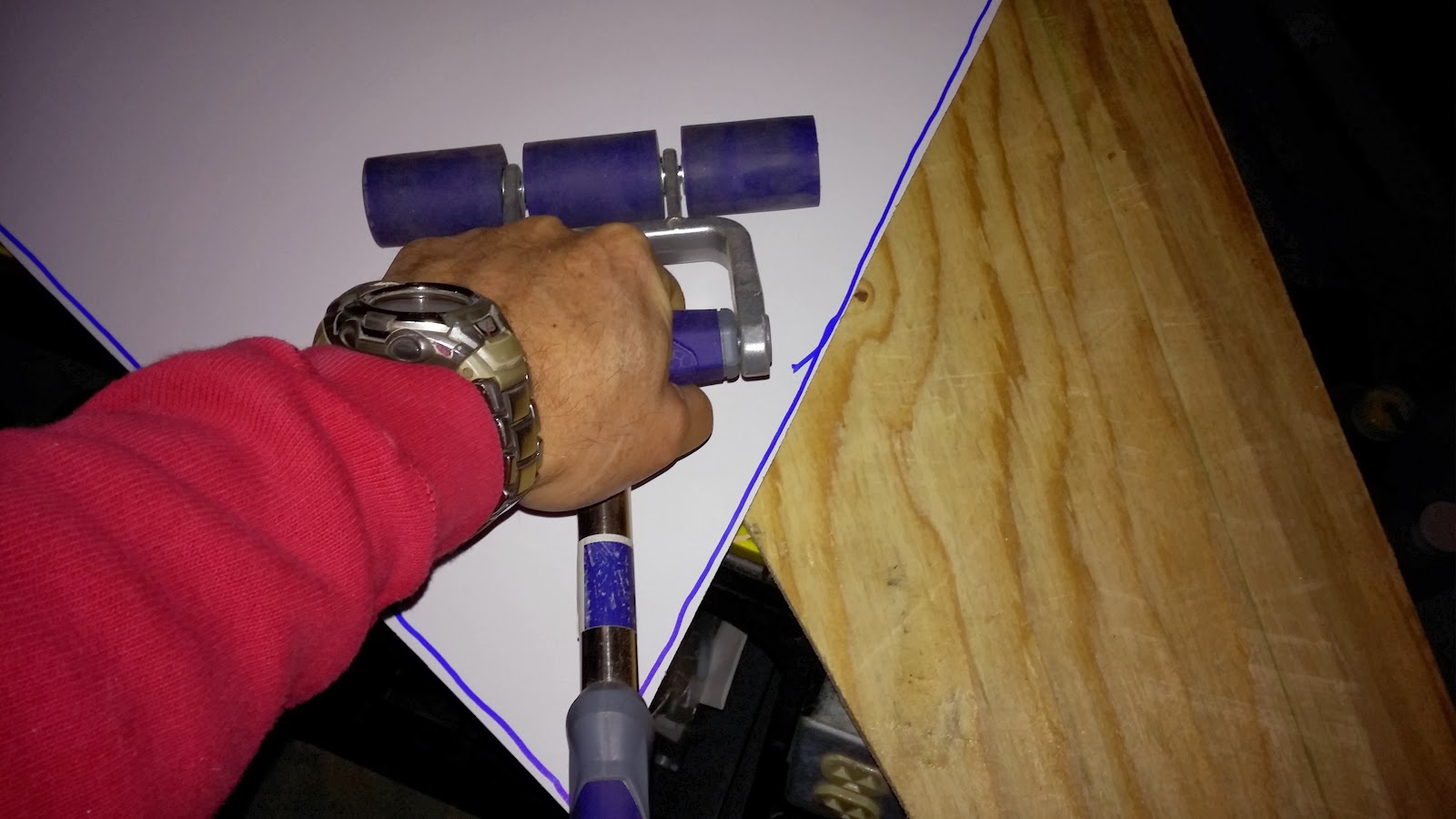
Now the time had come to adhere the Formica to the countertop. First, gotta assemble the tools...
The tools: Contact spray adhesive, scraps of wood, and a Laminate roller
The next step is to put the contact Cement both on the plywood and the bottom of the Formica...
After you can touch the Cement without it coming off on your finger, you put down the scrap wood spacers... DO NOT wait TOO long, or the cement won't work. The reason for the spacers is that once both contact cement coated surfaces touch, you are DONE and it is next to impossible to separate them. so you use the spacers so you can position the Formica properly so there is overlap on all sides.
I laid down 4 spacers here
Now I can position the Formica Just right...
Now I am ready to go. I pulled out 1 spacer (the one on the right) and use the roller to work out any air bubble that are underneath, working from the center toward the sides. then I pull out the next spacer, and do the same for the next section, and so on.
Using the Laminate roller (Sometimes called a J-roller, because some of them are shaped like a "J"
Press down HARD and work toward the edges
2 of the spacers removed, 2 to go...
Don't roll over the edge of the plywood or this will happen... fortunately, I think this will be OK.
All adhered, ready for trimming off the excess.
To do the trimming, I use a router with a Flush Cutting bit. In the picture below you see the router (upside down) and the bit. on Top, there is a screw that holds the Bearing, which is the shiny part below the screw, and then the cutting bit which is yellow. The way this works is, the bearing rides against the plywood edge, and since the bearing and the bit are the same diameter, the bit will cut the Formica flush with the plywood.
Then it is just a matter of going around the edge to trim the Formica. There are smaller routers, Aptly named, Finishing Routers, that do this job a little easier...
Now I just needed to cut out the hole for the Sink. To do this, I need a starting hole. So I used a Forstner Bit...
Then it was a matter of putting the router in the hole, and going around the inside of the hole.
The Starting hole...
almost cut out
All trimmed, ready for the Fiddles!
Now I needed a Faucet, after all, what is a sink with out a faucet? Useless! I wanted to have a Single hole faucet, as I had very little room to install it. I decided to use this one from Scandvik. It was a little expensive, but I think it will be worth it in the long run, and will look and work a LOT better than that kitchen sink sprayer that was in there before!
First you have to position it, and it helps to have a Brother in law to point out that unless you had it off center a bit, you wouldn't be able to operate the cold water tap.... Thanks Bro!
Then cut out the hole with a hole saw....
Cut the Hole
Then install the Faucet using the manufacturer's Directions...
Install the water supply....
Install the Sink.....
And Voila! a New Head! Kinda....
Then Just install the mounting bracket for the Shower head, and it looks like this!
Now, tell me true, Which head to YOU prefer?
Before
After!
Nice, bright and no ugly hoses Visible! Note the cover I made for them on the left... That will be a topic for another post....


Subscribe to:
Posts (Atom)


