Several years ago I stripped all of the 12-volt pressure-water system out of Cay of Sea. I did this for several reasons: I wanted to reduce my dependance on battery power; I knew that having pressurized water on board was an invitation to use more water, making stops for refills more frequent; I wanted to reduce the complexity of the on-board systems; it was also time to service the ancient electric diaphragm pump that powered the pressure system, and I either needed to make some changes in the way it operated, or needed to get rid of it altogether.
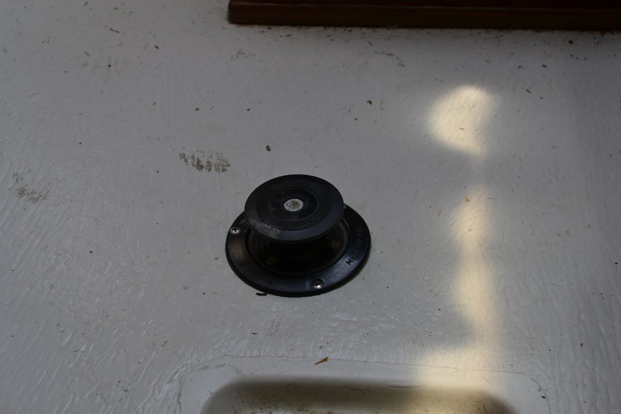
I replaced the single-circuit pressure system with two separate, discreet systems: one for fresh water for washing and showering, and one for drinking. The fresh water clean-up/showering water source is drawn from our forward 40 gallon tank (under the V berth) by the Whale Mk IV Tiptoe pump. This pump is mounted in the cabin sole near the companionway, and just adjacent to the sink, as you would expect. Our expandable capacity drinking water system is based on two collapsible 5-gallon containers that rest below the quarter berth stowage bin. These are plumbed to the galley sink through the engine compartment, and the water is drawn up by a hand-operated Whale V Pump. I have space in this stowage bin to carry an additional 10 gallons in collapsible containers. So we can carry 20 gallons drinking water and 40 gallons for other purposes. At some point before we go long-term cruising, I will replace all of the fresh water lines from the forward tank. After a thorough tank wash, that reservoir will be approved for drinking as well. Until then, we’ll keep the status quo, as the forward tank isn’t drained often enough to keep the water really fresh enough for drinking on our short cruises about the middle Chesapeake. However, 10-20 gallons in portable containers is plenty for short-range use, and easy to keep fresh.
I noticed at the end of last sailing season that we were going through 40 gallons of fresh water fairly quickly. When I investigated, I learned that the floor pump was beginning to leak at a fairly rapid rate: 15-20 drops per minute adds up to a lot of water over several days. Late last fall I ordered the rebuild kit for this pump (about $15), intending to rebuild it all winter. Now it’s spring and I couldn’t put it off anymore, so today I got to work on it.
The rebuild kit comes with an exploded view of the mechanism, which is important in order to see what parts go where, but there are no instructions regarding the process. This was a bit frustrating, as I could not figure out how to access the internal parts. I had to gently experiment on the pump body to get it apart. It appeared to be joined at the middle, but how it was actually held together wasn’t apparent from outside observation. I finally discovered that the halves are simply threaded.
I gently flexed the pump body in my shop vice, then gently held it in place within the vice without tightening the jaws. I inserted a rod into the pump outlet and applied counter-clock-wise pressure. The threads turned readily, but I hadn’t had enough leverage with just my arthritic hands alone. With the halves separated, I was able to easily access the valves and seals. You don’t need specialized instructions for this portion – just replace with the kit what you removed from the pump. There are several rubber valves, O-ring-type gaskets, and cup gaskets which go in strategic places. One thing you should know about: There is a circlip serving as a safety for a fitting on the end of the plunger. There is no way to get this clip off without circlip pliers. Just go buy a tool for $5-10 and you will save yourself a lot of frustration removing and replacing the circlip.
Reassembly and reinstallation was fairly easy, notwithstanding the usual frustrations of dropped fasteners, re-attaching supply and outlet lines, etc. Here it is mounted into its original location in the sole:
Perhaps there isn’t much demand for rebuilding these things – maybe that explains why I couldn’t find any information on the web for taking the pump apart. At any rate, I hope this post can help someone else as they look for rebuild information on this pump.
So why did it begin to leak after three years? Seems like it should have gone longer than that, with the light use we give it. I’m pretty sure that RV antifreeze shortens the life of the rubber internal parts. That’s why I’ve stopped using it – now I use my shop vac to dewater my systems. Otherwise, these are good, convenient little pumps.
Thursday, May 29, 2014
Rebuilding Whale MK IV Tiptoe Pump
Maintenance on a boat is a constant. Maintenance tasks are small boat projects that can provide a great deal of satisfaction. Rick aboard s/v Cay of Sea deals here with one which you might not yet have faced...


Thursday, May 22, 2014
Templating
Jeff and Anne aboard s/v Pilgrim are doing some major structural work. A part of that is fitting some repaired and some new bulkheads. Here Jeff demonstrates a time-honored technique for duplicating the curve of the hull on the bulkhead, a technique called "templating":
As part of our refit we are relocating the raw water intake & strainer. Originally the through hull and strainer were located in on the port side under the cockpit locker. We are moving them to the starboard side under the quarterberth deck. We believe the through hull valve and strainer will be more accessible on the starboard side. We are also creating a new mount for the starter battery under the forward end of the quarterberth.
The original layout of the quaterberth deck and access panel.
To ensure no salt water from the strainer or through hull ever finds its way to the starter battery we are fabricating a divider in the locker that will be fiber glassed to the hull.
Providing adequate egress to the work area and future relocation of the access panels necessitated removing the forward third of the quarterberth deck.
Forward third of the quarterberth deck cut away.
Transferring the location of the divider onto the arc of the hull took some creative measuring techniques. The line drawn on the hull in the image above marks the position we wish to install the divider.
To create a template that matched the curve of the hull I used scrap lumber and hot glue. The process began by clamping a 1X4 horizontally across the deck and in line with the future divider. Then, using 1/8” plywood I glued three vertical strips down to the hull.
Creating a template using scrap wood, tin snips, hot glue, and clamps.
Using tin snips to trim the plywood, I created a piece that connected the three vertical strips near the surface on the hull. I then attached on small pieces that contacted the hull at approximately 2 inch increments.
The small pieces along the bottom make contact with the hull at a single point.
Once completed I removed the template from Pilgrim and headed over to the shop.
In the shop I transferred the outline of the hot glued template to a piece of 1/8” plywood.
I connected the dots free hand with a marker.
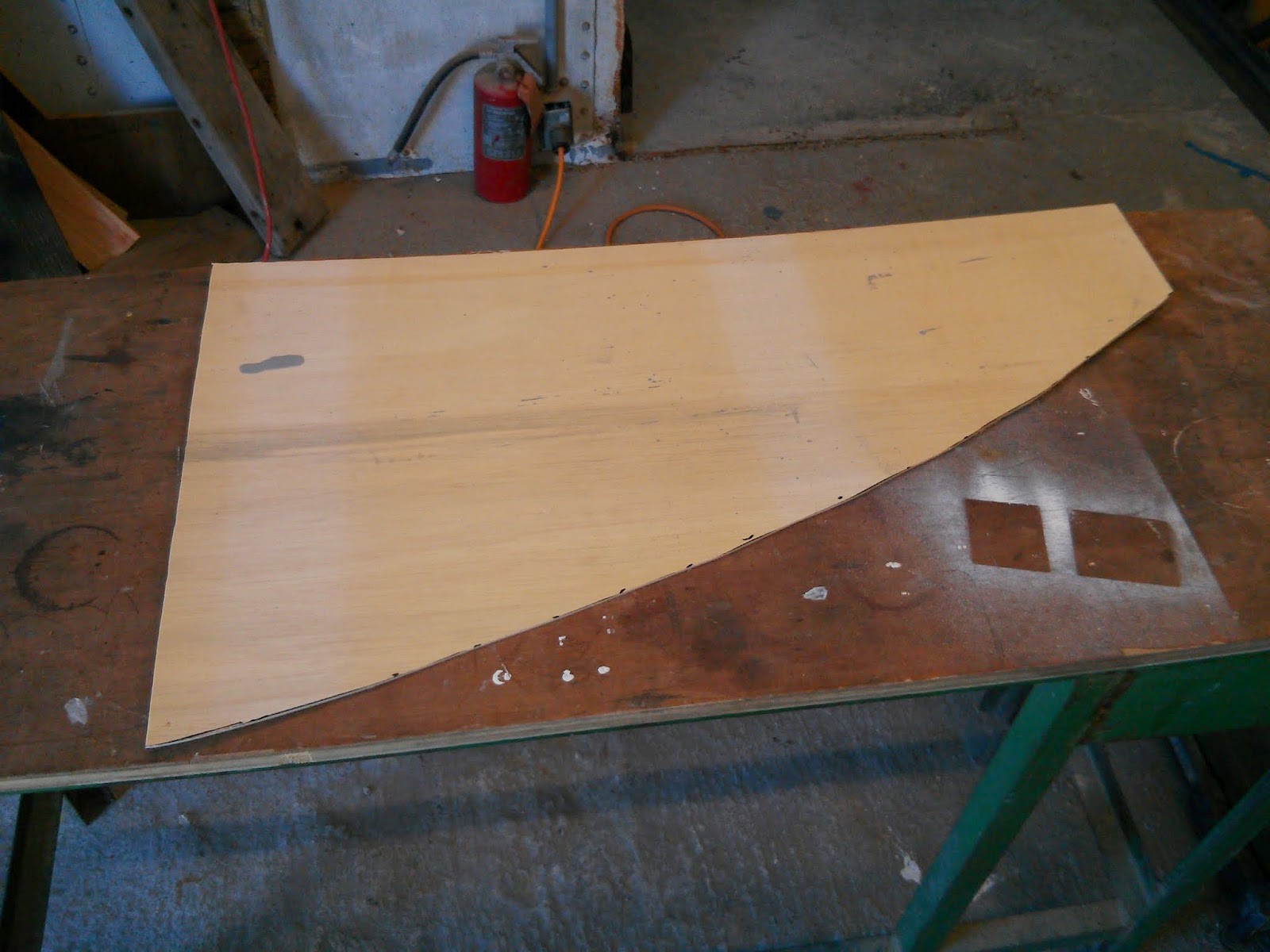
With the outline transferred to the plywood, I used a bandsaw to cut out the template.
The 1/8” template made a couple trips back and forth between the bandsaw and the quaterberth to achieve a good fit.
Once pleased with the fit, I transferred the outline of the 1/8” template to the ½” plywood that will serve as the divider.
The final piece fit precisely on the first attempt.
t Test fitting the 1/2" plywood Divider
The aft (upper in the image above) space will house the raw water intake. The forward space will house the starter battery and serve as storage for a tool box.
Using 1/8" plywood to experiment with the location of locker dividers.
Time to create templates for dividing the space up again… tool box on left. battery on right.


Tuesday, May 20, 2014
Rethinking space
Steve and Lulu who live aboard s/v Siempre Sabado have been doing so for long enough that they are having the opportunity to rethink some of their earlier decisions about interior space utilization...
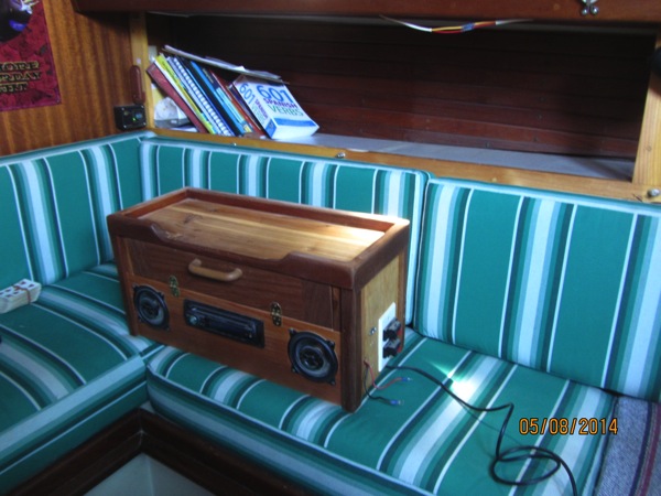
When we first got our Westsail 28, there was no stereo onboard. Matter of fact, there was pretty much nothing on board that wasn’t there when she shipped out of Costa mesa, California, back in 1977. Actually, there were a couple of major items like a relatively new Westerbeke diesel and a Webasto furnace but not much that you could see. Obviously, being music lovers, we needed a stereo. A car stereo was just the ticket although it became a little problematic where to mount speakers. Speakers tend to be a couple inches deep and the walls on the boat tend to be the thickness of one sheet of plywood, sometimes 1/4″, sometimes, 3/4″ but never more than that. So, the back side of the speaker would protrude into the space on the other side of the wall. Not knowing for sure where I wanted to put holes in walls, I decided to just build a custom cabinet and set it on the bookshelf that ran the length of the starboard side of the saloon.
It’s worked out pretty well so far. The little cabinet on top holds various chargers, disc cleaners, patch cords, etc. There’s a shelf on top where we stow the Netbook. But, we’re hurting for space and looking at this cabinet, I see a lot of wasted space. Something had to be done.
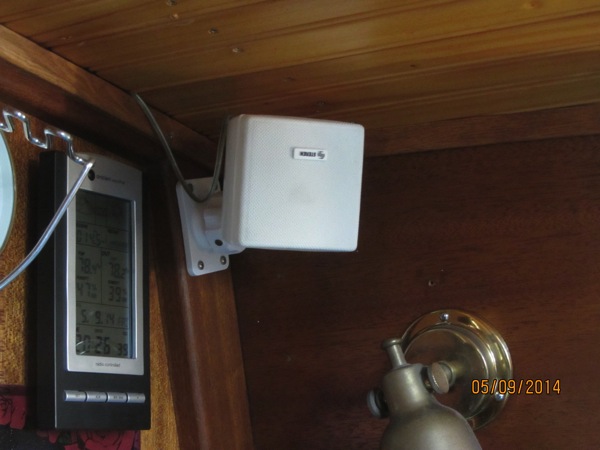
The first step was to rethink the speakers. In the past few years, the sound from small speakers has gotten better and better. Most of the surface mount speakers I found, however, were just too big for the cabin. However, in La Paz I found these little beauties:
You can turn them anywhichway and they’re small enough to not look out of place in our cabin. OK, speakers solved. Now it’s just a matter of finding a new home for the stereo.
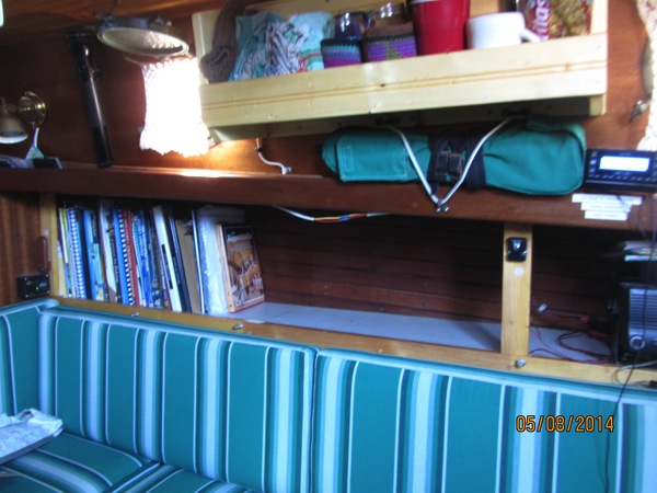
I knew I was going to do this project someday. I’ve been thinking and pondering on it for quite awhile. Well, now it was time to either take care of business or vacate the head, as they say. I entered into the project not really knowing how it was going to end. But, I knew the first thing was to pull the cabinet:
I was really pretty pleased with myself when I saw what a nice job I’d done on this cabinet. Seemed a shame to toss it but space is more important in this case. And look at how much room it frees up:
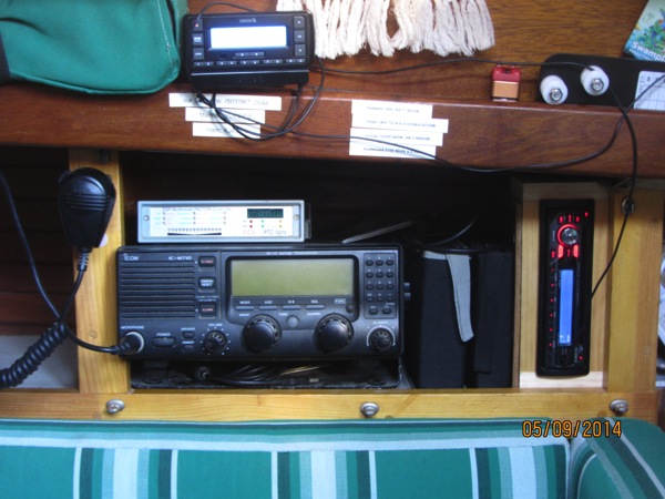
Of course, it only frees up the room if I don’t have to turn right around and fill the new space with the stereo. My original thought was that I’d build the stereo in, either on the shelf or hanging from the top of the opening. Then books could go either above it or below it, depending on how I did it. But, I wasn’t really liking this approach as much as I thought I would. The space just aft of the SSB radio was used for housing mini hard drives, blank CDs, and blank DVDs. The hard drives are currently in Flipper and will remain there until we finish our road trip. And by then, who knows? Maybe I’ll have consolidated everything I have onto a couple of 10 TB hard drives which are sure to be available by then. I’ll worry about that when the time comes.
So, what did I do? Well, I decided to use the former hard drive storage space for the stereo. Trouble was, once I built an enclosure around the stereo, the space was no longer wide enough. It would have been doable back when I had a shop that had a thickness planer in it. I could just plane the wood down to the size I needed to make the enclosure fit. But that’s not the case so I had to work with what I had which was 3/4″ thick wood.
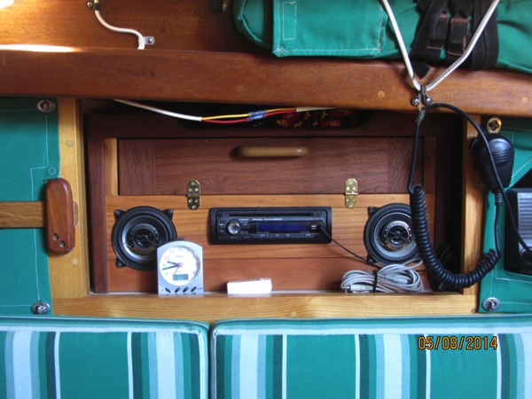
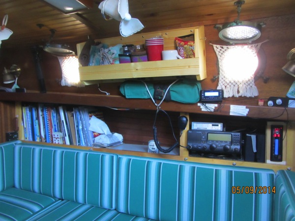
I remember the first time I ever saw a car radio mounted vertically instead of horizontally. It was on “Route 66″. I don’t know which model year it was but I think it was around the time of the advent of the Corvette Stingray (what a cool name!) and there was a shot of either Buzz or Todd hitting a button on the radio. The radio looked just like any radio except that it looked like it had been mounted sideways, except for the fact that all the letters and numbers were set up so that it was obviously supposed to be mounted that way. Cool. Different and therefore, cool. Like the vertical headlights on the first Buick Riviera or the fastback on the first Plymouth Barracuda. Different, therefore cool. Anyway, I decided that there was absolutely no reason I couldn’t mount my stereo “Stingray-style”. Of course, the words on mine are all sideways but I can adjust. We almost never play CDs but, if we do I’m sure they’ll play just fine. If they wouldn’t, the Sony Discman never would have worked. So, here it is, my Westsail Stingray:
The carpentry is a little plain but it works and the system sounds great. And look at the resulting space:
BTW, the overhead (ceiling) I installed way back when proved its worth once again. I needed to run speaker wires from the forward-starboard corner to the stereo, the length of the saloon. I was able to hide the wire above the pine boards and only had to remove two boards to do it, not the entire overhead. Made the job much quicker and MUCH easier.
Tomorrow I have to figure out how to run wires to the new outside speakers. I mean I have to figure out how to run wires NEATLY to the outside speakers. Hmm. Wonder how I’m going to do it.
Friday, May 16, 2014
Hydrocoat Reevaluation and Bottom Paint Renewal
I am convinced that sailors are curious. The most curious make investigations and share the results with the rest of us. Rick over on s/v Cay of Sea is one such - he is trying the newly offered water-based bottom paint Hydrocoat. Here's his report of the current status...
I’m back. It’s been a long, cold winter here in the moderate climate mid-Atlantic region, and the weather has not been cooperative except for one or two isolated days. We finally got a break today, so I took advantage of the clear skies and moderate temps.
Back in December I reported glowingly about Hydrocoat. I am still impressed with it, but have moderated my praise slightly. I prepped the boat for paint today and got to take a good look at existing paint. It was in good shape, for the most part. There were a few chips here and there where my preparation must have been less than good, but it was mostly intact. However, the power-washer guy had originally told me there were two barnacles when he washed it. He was obviously exaggerating, as there were certainly more than two. But there weren’t many. Small clusters port and starboard at the bow, and on the leading edge of the rudder. While the barnacles were long gone from power washing, you could see where they had adhered. So the paint’s pretty good – two years of service with little hard growth.
I decided to repaint the hull and not try for three seasons, as I didn’t want to chance having the paint completely fail mid-season and leave me having to scrape the hull often to finish out the year.
I gave the hull a quick sanding, and I’m glad I did. This really smoothed the hull again, and I discovered that the existing paint coating isn’t very thick. It was fairly easy to sand right through to the old epoxy paint, which looks to be one of the original layers of paint laid down those many years ago. Thin coating is good, as this is an ablative paint, and I don’t want it to build up like it had before I stripped it all off three years ago.
The sanding took about an hour. I was able to remove all of the water marking at the water line, all the collected dried scum where the travel lift straps were, smooth out all the paint and start with a fresh slate. I used my 5 inch random orbital sander connected to the shop vac, wore my respirator. Wish I had a photo of the funny lines on my face from the respirator.
Then I wiped down the hull with water and a sponge, taped the water line, and started to paint. Painting took longer than I expected for some reason. Amazingly, I used less than a gallon of paint. I guess the paint goes quite a bit farther with a smooth hull. There was about a pint of paint left for painting the keel bottom and under the jack stand pads.
Another nice thing about Hydrocoat: When you get home, it washed right off with soap and water. Got it in your hair? Two good shampooings and it’s gone. Try that with solvent-based paint!


Thursday, May 15, 2014
Wire Cable vs. Stanchions
Over at Sail Delmarva Drew puts the test equipment he has built to work investigating the ability of various recommended lifeline materials to resist chafe thru the stanchions...
I've been investigating chafe protection and Amsteel as it relates to lifeline replacement. Certainly, wire cable is the gold standard. But now I'm not so sure....
After an hour of sawing back-and-forth through a 10mm hole in SS tubing, it had eaten a nice groove and built a corresponding burr on the inside:
After 1 hour.
And though the wire did not look very worn, when we flexed just a bit there was a different story....
Also 1 hour. The damage was not apparent until flexed. Most of the broken wires were inside.
How did Amsteel fare, in the same hole? Before the wire created the burr? Much better with very little wear in an hour. Afterwards, no as well, but still the damage was little more serious than that to the stainless cable. Given that I plan to use 1/4 Amsteel, which is nearly twice as strong as the cable to start with, I'm feeling OK. 1/4-inch it is sufficiently strong that even after 10 years in the Chesapeake sun (not so strong as the desert southwest or tropics) it should have equivalent strength, and with proper chafe guards, the strength loss in the holes should be less than wire. Protected from the sun, the pass-troughs may be the strongest part by then.
How does Amsteel like the new hole? Not so bad as you might think and about the same as it like the raw hole, just after I drilled it without deburring. By way of comparison, after the hole was deburred it showed ~ 1/3 this much wear, and if coated with Spinlock RP25, no wear after 2 hours (840 cycles).
After 1 hour on the wire cable gouged hole. About the same as a raw drilled hole, yet much worse than a polished hole.
Alternatively, I tried a dyneema anti-chafe sleeve floating for 3 hours. It could have run for 100 hours without showing wear.
A floating dyneema cover reduces wear to zero.
By way of comparison, this hole wore a polyester line through the cover in 20 seconds and in half in 5 minutes. Amsteel is tough stuff.


Tuesday, May 13, 2014
Tip tip
This post originally appeared on Windborne in Puget Sound


Have trouble with polysulphide, silicone or 5200 curing in the tube tip between uses?
Here's a tip: wipe the tip clean before you snap the cap back on. See that thin ridge that goes around the tip? That is supposed to seal, plastic to plastic, with a mating groove inside the cap, making a *snap* when you push it on.
None of the compounds I listed above "dry" - instead they harden by reacting with water vapor present in the air. And the reaction is designed to propagate over significant distances of the material, so that thick layers will cure all the way thru. Therefore if there is a continuous layer of material reaching from outside the sealing ring and past it into the tip interior, the reaction will proceed into the tip and then eventually into the tube itself.
Thinking of this as if the tube were filled with polyester resin, and the air was saturated with MEK peroxide catalyst will give you a clearer picture perhaps.
Just before the final capping, extrude some of the contents, flushing the end bit which has been exposed to moisture. Then thoroughly wipe off the tip and install the cap. You'll be surprised at how little in-tip curing there has been the next time you need to use the material.
Thursday, May 8, 2014
Winch Covers - a great rainy day project
I don't know about where you live, but we have had a lot of rain here in Seattle lately. Jeff, living aboard s/v Pilgrim, gives us here a great rainy day project. But more importantly, we have a confession that he committed the nearly unpardonable sailors' sin of actually following directions!
Success! Another project to tick off the Pilgrim to do list.
Rainy weather may have prevented work out in the boat yard today, but it gave me time to get some sewing done.
Starboard cockpit winch - naked and exposed to the sun.
We purchased Pilgrim with two Barient/Barlow 25 self-tailing winches in the cockpit. The rope jaws on these winches are plastic and susceptible to UV damage. I’ve learned that Lewmar purchased Barient and replacement parts are now very difficult to find. Thus the need protect the winches with sunbrella covers.
Fortunately Sailrite recently posted a how to video on making winch covers . I followed the directions on the video nearly verbatim – unusual for myself.
Much of the canvas work on C’est la Vie was “toast” colored Sunbrella so we have many spare remnants around for small projects. I figured the light brown color would work well alongside Pilgrims wood cockpit combing. The only other necessary component was a couple short lengths of bungee cord.
All components of the covers ready for assembly.
Sewing the top piece to the vertical sides is a bit tricky, but as the video recommends going slow eases the process.
Tensioning the bungee on the first cover to be completed.
I could not wait for the rain to cease before running out to the boat for a test fit.


 |
| Test fitting portside cover |
Success! Another project to tick off the Pilgrim to do list.
Tuesday, May 6, 2014
The Little Jobs...Doo Daa
Ken & Vicky, who live aboard s/v Painkiller give us a look at several small projects. And they demonstrate the benefits of scrounging thru the bins at boaters' second-hand stores!
Since arriving in St Augustine last Monday we've pretty much been taking a deserved break from the 58 day work sprint on the hard, in Fernandina Beach. Dang, it feels good! As some of you know, on a boat there is always plenty to do and improve on so taking a full all day break can be harder than imagined even if your trying. On the way here we had engine problems, nothing catastrophic just a pain in the ass issue than seems to be getting somewhat better and another full run day should expose more clues. I'm tired of looking at it and I've spent way too much time in the engine compartment over the last few weeks. So I pushed it aside mentally for now, feeling we could still make it to our next destination south with little problem and deal with it there in a more serious mind set.
We always had intentions to stop here to do some trading at the Sailors Exchange, a sort of conglomeration of used and a few new boat parts all sorted (kinda) and stacked. The crew is very friendly and they're looking to make a deal as much as your looking to get a deal. If you keep that in mind, trading with them is a good experience. We had a pile of good thru-hulls that I had no use for, I kept a few, and offered them three, a 1 1/2" and two 3/4", they right away offered a fair price that we could have in store credit. Even when we brought stuff to the counter to buy they were more than generous at pricing it to deduct from credit. To me, they were completely fair and a pleasure to deal with. Win, win.
This is my first boat that didn't come with a nice flagstaff for the stern. I always was a flag guy and always enjoyed the routine of setting it at 8:00 am and taking it down at sunset. I could have made one, with time that I didn't have, but thankfully we found this (hanging upside down in the picture getting varnish) one at Sailors Exchange in need of a good sanding and varnish stuffed in a corner. Also got a base mount for it. With the dingy davits and other stuff crowding the stern rail it's a bit of a challenge picking a spot. More than likely it will go on top of the davits after I fabricate some sort of platform for the flag base mount to mount on.
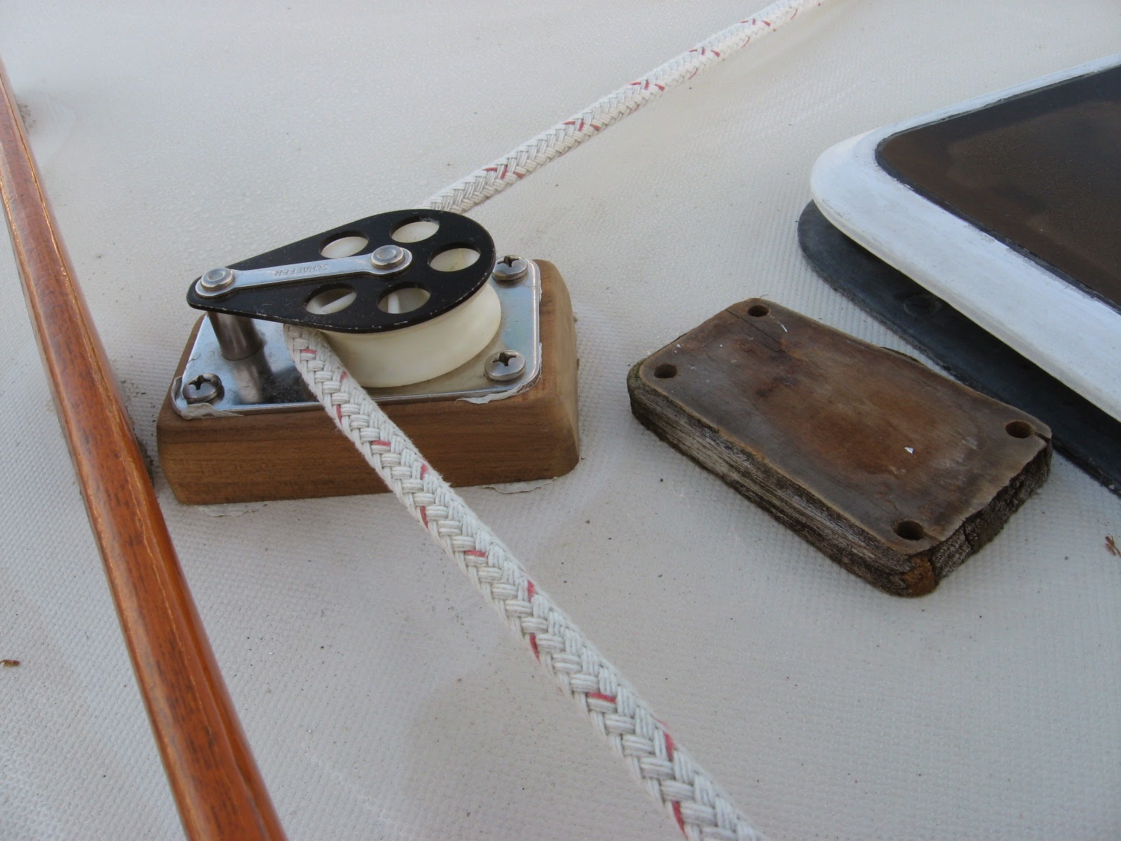
This old mainsheet teak cheek block had seen better days, not to mention it was too low so it dragged along the cabin top creating more friction. I had the teak, Sailors Exchange had the longer bolts and it was down right fun shaping this block in the sunny cockpit. The hardest part of that job was the dissembling of the headliner down below and carefully putting it back.
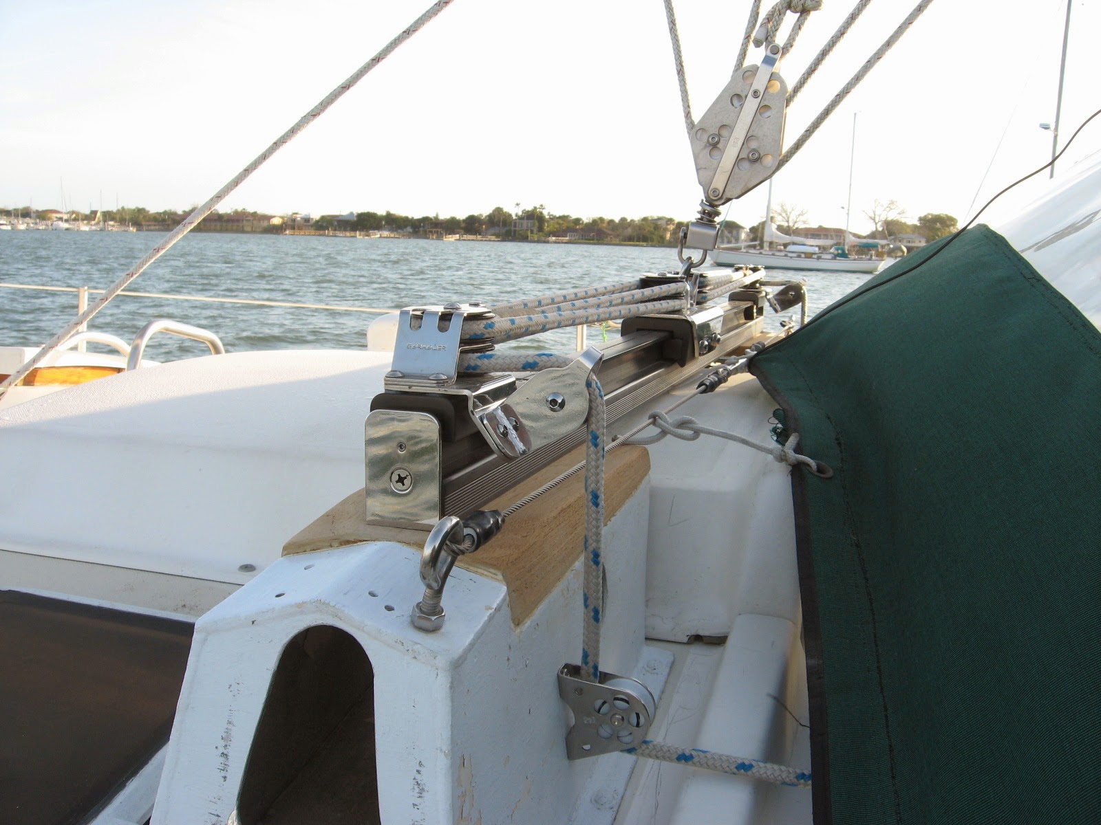
At the store, I looked and looked and shuffled through bins and bins of blocks and sleeves and could not find what I needed to complete the new traveler assembly I installed back at Tiger Point, so I ordered what I wanted through them, at their discount plus a little. The fairlead block at the bottom of the picture lets the traverler sheet enter under the future dodger just above the coaming that it will snap to. This will insure that under the dodger at this point will stay as dry as possible. The mainsheet (block in above picture) also enters under the dodger in this area. That green canvas thingy that's pretending to be some sort of flat dodger that's tied to that wire, stretched between two eye bolts is most definitely on it's way out.
If you are ever in the need of bronze plumbing you will be blown away at the cost of new. As we should all know, plain old brass is a complete NO GO on a boat with anything to do below the water-line. The sailors Exchange is the perfect place (you must have time and patience to dig and push through and dig and sort through bins chuck full of fittings and search everywhere all around for other bins) to pick up some of the very expensive parts at a mere fraction of the cost!!!!! This assembly or an assembly something like it will be the new raw water manifold. It will feed multiple sources of salt water throughout the boat from one thru-hull and strainer.
Other little jobs took place this week also, some resorting of lockers, (that will take years aboard to finally end) mounted a LifeSling etc, etc. The never ending pile of what I like to call Doo Daa!


Subscribe to:
Posts (Atom)


