There are many ways to strap a GoPro on when kiting. You can mount it on your kiteboard, your helmet, your kite strings, or even (*groan*) a selfie stick.
We like the shots we get with our GoPro strapped to the main strut of our kite, near the leading edge and this is the mount I made to do so. I made wide strap out of Crypton Ultrasuede scraps I had aboard from our cushion covers with two strips of 2” velcro. I used some Seam Stick at first so I could take it to the beach and fit it onto a few different size kites to make sure it would work before I sewed it.
Then I took neoprene from an old old laptop case and made a pocket for the GoPro. In the flap on the open side of the pocket, I put a snap in plastic tarp grommet and some kite string (spectra type). The kite string was cut long enough so that one side could be tied to the pump up loop on the kite and the other side to the GoPro in case the case failed.
With the case and camera mounted on the kite, I outlined the lens of the GoPro with chalk, removed the case, and cut out the lens hole.
We accidentally tested the backup string when we crashed the kite so hard that the camera popped out through the lens hole (!!!) and the string kept the GoPro dangling from the kite while we sailed back to the beach and removed it.
And here is what we get with it. Not as flexible as a drone, but dirt cheap, and very satisfying.
Wednesday, December 23, 2015
Kite Mount for GoPro
Livia and Carol, living and cruising aboard s/v Estrellita 5.10b have been kiting their way thru paradise. But how do you proove that to others? You need a kite mount for your GoPro camera...


Wednesday, December 16, 2015
Replacing the Leaking Quarterberth Port
Jeff and Anne continue their refit of s/v Pilgrim. Today we follow along with them as they replace a leaking port, a project many of us could have to face. The unusual part of the project is the thickness of the hull at the port location.
Jeff made this as three posts; I have condensed them into one.
Jeff made this as three posts; I have condensed them into one.
While sanding in the engine compartment, a passing a rain shower alerted me to how badly the old, plastic quarterberth port was leaking. All the other ports in the Pilgrim are New Found Metal Stainless Steel ports, installed by a previous owner. Replacing the only remaining original plastic port was on the project list. Watching row of steady drips along the starboard side wall of the engine compartment elevated the project priority.
We believe the plastic port in the quarterberth was installed at the factory in 1979.
Frequently after rains I check the quarterberth area for water intrusion. Never found any signs the port was leaking. It never occurred to me to check the engine compartment. The leak originated around the outer flange of the port. The water then dripped down thru the void between the fiberglass wall of the cockpit foot well and the ¾” plywood cabinetry wall of the quaterberth.
The original port, set in copious amounts of silicone sealant, heartily resisted removal. Ultimately the combination of a razor knife and pry bar won the day.
The exterior view of the hole remaining after the port was removed.
After sanding down the surrounding surfaces, I filled the nearly 1-1/2” wide void around the perimeter of the opening with trimmed down pieces of a pressure treated 2” X 4”.
Fitting treated wood plugs into the void around the perimeter of the opening.
The wood plugs fit snuggly. Once in place, I mechanically fastened the wood filler to both the outer fiberglass and the interior plywood using flat head stainless steel screws.
Filling gaps and irregularities around the opening with thickened epoxy.
Next, the remaining gaps and irregular surfaces were filled with cabosil thickened epoxy. After sanding down the initial round of epoxy filler, the fairing began.
Round one of fairing viewed from the interior.
Fairing required two rounds of epoxy thickened with a micro-balloon filler (q-cells). Each round of filler was followed by additional sanding.
Two rounds of fairing completed. Now ready for primer.
The interior surfaces were finished with two coats of latex primer and two coats of exterior grade latex paint.
The interior completed. Test fitting the masked acrylic window pane.
Since we intend to use Pilgrim’s quarterberth as a storage area only, we chose to install an acrylic window pane rather than a new opening port. We realize not installing an opening port will reduce ventilation in the area. We have scrap pieces of tinted acrylic on hand. New ports are very expensive. Using the acrylic will save us money. The window will provide natural lighting for the storage area.
View from the interior with the new window installed.
See our Quarterberth Refit Photo Album for images and notes current progress on this project.
Next up, the outside story… fabricating and installing the new acrylic window pane.
Our previous post, Replacing the Leaking Quarterberth Port, the Interior Story, explains why, and how we removed the original port. The post also shares our reasoning for replacing the port with fixed pane window.
As many boat projects are apt to do, the exterior story begins with… creating a template.
Creating a 1/4" plywood template of the window pane. Yes, that is an electrical tape canister we are using for the corner radius.
The template will allow us to “test” the aesthetics of the panel prior to cutting into our limited supply of acrylic material. The template will also serve as a guide for the router bit used to trim the acrylic. ½” plywood was my preferred template material. Unable to find an appropriate piece of scrap we used ¼” plywood.
Pleased with the look and fit of the template, we then transferred the shape to the masked acrylic.
Template dimensions transferred to the masked acrylic sheet.
Ok, time for a disclaimer… our experience working with acrylic, Lexan, Plexiglass, and similar materials is very limited. We welcome any comments or suggestion on working with these types of materials.
The material we are using is ½” thick Chemcast Cell Cast Acrylic Sheet. We reclaimed the scrap material from a project on another vessel. Since the material was previously installed it lacked the protective coating found on virgin material. When possible we kept the pane masked with painters tape during the install process.
Prior to cutting the actual pane, I experimented with various cutting tools and techniques. The jigsaw with Plexiglas specific blades generated too much heat. The heat melted the acrylic and created a rough, scored edge. Perhaps the jigsaw blades would work better on thinner material? Using the hand held circular saw with a multi-purpose blades (24 to 40 teeth) yielded similar results to the jigsaw. The best solution I found was to use a fine crosscut blade (90 teeth) in the circular saw to rough cut the acrylic. Then use a router with a flush trim bit for the final shaping.
With the template as a guide, I used a router with a flush trim bit to clean up the edges of the acrylic window pane.
I clamped the rough cut pane atop the plywood template. The template then served as a guide for the flush trim router bit. Since the guide wheel on the router bit transfers any irregularities from the template to the finish material it is important to sand down the rough edges of the template. Yeah, I learned this the hard way.
Unfortunately the painters tape masking did not play nice with the router. My solution…
Masking the base of the router proved more effective than masking the acrylic face.
Remove the masking from the acrylic and place a couple strips of masking on the base of the router. Masking the base of the router worked for both the flush trim bit and the round over bit used to radius the outside edge of the pane.
Next the edges of the acrylic were sanded beginning with 220 grit and progressing up to 600 grit sandpaper. Sanding the edges up to 600 grit brought them back to a dull, smooth surface. I certain by a polished edge could be achieved if so desired.
Part 1 of the Exterior Story focused on shaping the window pane (Link: Replacing the Leaking Quarterberth Port, the Exterior Story – Part 1.) Thanks to everyone the left suggestions and links on the last post. Now we are on to installing the window.
Drilling over-sized holes for fasteners in the acrylic window pane.
Due to thermal expansion / contraction the pilot holes for mechanical fasteners need to be over sized. I also drilled a slight counter sink on the exterior pilot holes to provide space for butyl tape bedding. This work was all done on a drill press.
Clamping window in place to test fit, mark fastener locations, and scribe window opening on interior face.
The window moved from the drill press to a test fit on Pilgrim. While the window was clamped in place we marked the fastener locations on the exterior. On the interior we used a marker to trace the window opening onto the masking.
Using a marker to trace the interior window opening onto the masking.
After removing the pane, we gently ran a razor blade along the outline of the opening on the interior of the window. This allowed us to remove the section of masking in contact with the hull while leaving the remaining window masked. We then drilled the pilot holes the cockpit wall.
Acrylic in contact with hull exposed and pilot holes drilled.
We are using #12 stainless steel pan head screws to mount the window. To allow for thermal expansion we included a neoprene washer between the head of the screw and the pane of acrylic. The screws are bedded with butyl tape. We are also using butyl tape to bed the window.
Applying butyl tape to fasteners and acrylic.
We applied three rings of ¾” wide X 1/8” thick butyl tape to the exposed acrylic on the interior face of the pane. We have found Amazon to be a good source for butyl tape. Here is a link to the tape we are using on this project – Dicor Butyl Tape.
Fortunately the installation occurred on a hot, sunny day. Both the acrylic and the butyl tape are easier to work with when they are warm. In cold temps the acrylic is less flexible and more prone to cracking. The cold butyl tape is much more firm and less likely to form into a good seal. If completing this project in the winter, then we would have used a heat gun to warm the assembly prior to attempting the installation.
The installation went smoothly. We over tightened the pane slightly until we observed butyl tape squeezing out around the entire perimeter. Then we backed off the screws until the neoprene washers returned to their original shape ( approximately ¼ to ½ a turn.)
Using a plastic "knife" to remove the excess butyl tape
We use a plastic “knife” to cut away the excess butyl tape.
The completed installation.
After completing the install, overnight thunderstorms confirmed the new window is water tight.
See our Cockpit Refit Photo Album for additional images and other projects associated with the cockpit.


Tuesday, December 1, 2015
I Hate Yellowjackets
This post originally appeared on Windborne in Puget Sound
You're at a quiet anchorage in late summer. There is a slight breeze - just enough to keep you comfortably cool. Then you get out some food or drinks in the cockpit, or begin to bait a crab trap.
And then here they come.
From out of nowhere, you will find your boat surrounded by a buzzing horde of yellowjackets, come for the moisture, or more likely for the meat. Once the first scout gets back to the nest with the news of free eats, you are doomed.

We learned this trick in Canada at Ganges Harbor. The Tree House Restaurant there has outdoor seating - it should be swarming with yellowjackets. And one occasionally does fly by. But you can eat outside in peace. Why?
Because they have these brown paper bags inflated and hung all over. Our waitress explained that the yellowjackets see the bags as paper wasp nests and stay away accordingly. Maybe they are natural enemies? I don't know. But give it a try - it works!
Tuesday, November 24, 2015
Laundry
If you're cruising or maybe just off the dock for weeks on end, laundry becomes an issue. TC & Kelly aboard s/v Wind Strider share with us their method for producing clean clothes while away from shore:
In my-not-so-humble opinion, laundromats suck. Marina laundries even more. Few and far between, they are a quality craps shoot. Tending to be hot and steamy, they may or may not have fully functioning machines. Even if the washers function, there are other probable problems like not getting all the soap out. Then, what was left behind by the previous user? For instance, boat waxing rags leaving all kinds of muck in the machine? Dryers...well, they take forever. Everything is also expensive. Further, the facilities tend to be crowded...one is lucky if the crowd is friendly.
No sir, I don't like it and would rather spend time on the boat vice a marina laundry.
So, a search for an alternative was deduced, experimented with and the results are presented.
The basics: Wash and dry. There may be a few intermediate steps in the process; sort, load into water with cleaning agent, agitate, wring out cleaning water, load into rinse water, agitate, wring. Most of these are normally done by automatic washing machines. Hands on are only required for the sorting, initial loading and transfer to the dryer. Lucky these are modern times and we are not living in grandma's era huh? I promise I don't envy grandma and I am too lazy to do all she did.
First, an admittedly smart assed assumption: Everyone is familiar with solar clothes dryers. This is the clothes drying method used since ancient days where clothing is placed such that circulating air and the shining sun can dry them. Modern versions generally include a stretched, horizontal line and the use of clothes pins to secure the clothing to the line. Sail boaters know lifelines and sheets work well for this purpose.
How to do the wash? I had stumbled across the Wonderwash a few years ago and thought to purchase one. Reviews were good, but it is a one-use-product, only used to do laundry. I don't like one-use-products aboard, especially fairly large (size of a small microwave) one-use-products. There is just not enough space.
So, alternatives were looked for. The internet and youtube can provide a lot of information, some is quite entertaining and I came across this 'cheap and easy DIY washing machine'. Now this could be done easily as both the bucket and holey bucket were already aboard! The on board bucket, besides being a just a bucket, seconded as the bottom half for a 'Bucket Head' vacuum cleaner. With a lid, the holey bucket, suspended into the water next to the boat, is a live seafood container also known as a 'crab condo'.
Instead of the drilled plunger for an agitator though, a Breathing Mobile Washer was purchased w/o a handle. It is small enough to store very easily (inside a bucket). The boat hook already aboard has a compatible screw-in portion and could double as a handle.
So, bucket and agitator: Check. How to get rid of the water (wring) efficiently?
It is important to effectively get rid of the wash cycle water prior to rinsing. The more soapy water removed, the less rinse water required. While the sit squish method in the video worked, my 220 pounds did not 'wring' the clothing well enough and they came out wet. The spin method just took too long and was labor intensive. Hand wringing is a viable option. But unless the clothes-damaging, around-the-lifeline-stanchion method was used, the bare hand method is just not effective enough.
Then a buddy suggested a wringer, an actual hand crank, roller wringer like grandma used to use. They are still available! Several were looked at and the DynaJet BL-38 was selected because of its simplicity. A couple Magma T10-380 grill mounts easily replaced the stock mounts to enable rail mounting. Mounting and adjusting the wringing pressure will be dependant upon the model purchased and your personal preferences.
Bucket, agitator and wringer: Check. Cleaning agent....
Strider only holds 30 gallons total fresh water. Tough to do laundry with so little. The first thought was to use salt water for the wash (detergent) portion then rinse with fresh. Via cruiser forums, this was a bad idea. More fresh water would be used to rinse the salt out than if fresh was used in the first place. It is critical to get the salt out! Salt will attract water (hence rice in the salt shaker) and the clothing, or bed sheets, will always feel damp. Other forums discussed how much soap to use etc.
Then a reference was found to use ammonia instead of detergent. An ancient cleaning solution, the Romans actually collected urine to convert to ammonia for use in their laundries. Now, before anyone says 'yuck' or 'smells bad' or 'are you nuts' or 'piss' - ask yourselves how did the Romans get their togas so white? And they did not walk around smelling like urine (BO maybe, but not urine).
So ammonia has a strong smell. Use it in a well ventilated area like the stern of the boat. Further, it is an organic, completely natural, disinfecting cleaner and not a bleaching agent - it will not change the color of the clothes. Last, and best of all, it evaporates. That's right, evaporates. Translation: No Rinsing is Required.
How much: 3/4 cup clear ammonia to 2.5 gallons of water is a good baseline and was found to work very well. Make sure to get clear ammonia and not sudsy ammonia. Sudsy ammonia has a small amount of detergent...which will require rinsing.
Bucket, agitator, wringer, cleaning agent: Check, check, check and check.
The rest is just technique. 2.5 gallons of water and 3/4 cup ammonia in a 5 gallon bucket is not a lot of water/space so small loads are required or the clothes will not get an adequate agitation. Since the wash water/ammonia solution will be used over and over, sort the clothing into small loads from lightly soiled to most heavily soiled and this is the order of washing: Lightly soiled to more heavily soiled.
Details: A small amount of clothing was loaded and agitated for about 2 minutes. A lid was put on the bucket to prevent ammonia evaporation and load left to soak. After about 30 minutes, the load was again agitated for about 2 minutes. The wash cycle was now complete! The trick now was to conserve as much of the wash water as possible. Items were removed one at a time and some water was hand wrung back into the bucket. Then the item was put through the wringer. Smaller items were folded a couple times to increase the wringing pressure. Larger items, like towels and bed linens had to be folded to make them narrow enough to fit into the wringer aperture. Each wrung item was then set aside for hanging. After the entire load was wrung, the next load was placed in the bucket and agitated for 2 minutes. While the new wash load was soaking for 30 minutes, the wrung load was hung to dry.
100% water recovery is not possible and if there are too many loads, the water level or load amount will have to be adjusted. If the loads are really dirty, a fresh batch of water/ammonia may be required. Your option of course.
All in all, each load required about 40 minutes from loading to hung for drying. 30 minutes was soaking time, essentially down time available for something else like relaxing or another boat chore.
In the end, the left over cleaning solution was often pretty dirty. Most times, the dirty water was just poured over the side (organic, natural remember) via the cockpit drains to help keep them clean. Relatively clean solution was used to clean the sinks, countertops, around the toilet etc.
The results were impressive. My wife, a skeptic with a nose able to detect a mouse fart, was thoroughly amazed and loved the results. Fresh, clean, crisp bed linens! The boat buddies with us decided to try it and are now purchasing their own equipment.
Cost:1 Home Depot buckets ~$3.00 (free since it was already aboard)1 Home Depot bucket lid ~$1.00 (free since it was already aboard)1 Whisper w/o handle ~$14.001 DynaJet Wringer ~$140.002 Magma Grill Mounts ~$50.00 eaAmmonia cheap
The only cost I don't like was for the grill mounts. They work great...just hate the cost.
The formula is simple: 2.5 gallons fresh water + 3/4 cup ammonia + agitator + wringer + clothes line + sunshine = fresh, clean, crisp clothing.
Tuesday, November 17, 2015
A Civilized Idea
We recently returned from a trip to the UK; while there we saw a bathroom fixture which was ubiquitous there but virtually unknown in the USA: the heated towel rack. Do you have any idea how wonderful it is to wrap yourself in a warm towel after a shower? Probably not, sadly. Oh, and the towels dry off much sooner hanging on a heated rack too. It's a very civilized idea.
Adam and Adrian recently installed one of these on nb Briar Rose. Theirs is hot water heated - a very common solution in the UK, where forced air heating systems are virtually unknown. If you have hot water heat in your boat, this would work for you too. (Electrically heated models are also available and only draw 75 watts or so).
Adam and Adrian recently installed one of these on nb Briar Rose. Theirs is hot water heated - a very common solution in the UK, where forced air heating systems are virtually unknown. If you have hot water heat in your boat, this would work for you too. (Electrically heated models are also available and only draw 75 watts or so).
I have to work all weekend, but Adrian went up to the boat today -- taking much much longer than usual because of all the bank holiday traffic. While Briar Rose has been at Calcutt, the leaking radiator in the shower room has been changed for a heated towel rail.

Tuesday, November 10, 2015
New Companionway Drop Boards
Jeff and Anne on s/v Pilgrim take on a small project that many, many boats need:
Rare is the boat project that can be completed in a single afternoon.
Pilgrim's tired, teak drop boards. Pilgrim arrived in Beaufort with three teak companionway drop boards. The existing teak drop boards are both too thin, between ½” and 5/8”, and too short. Due to the inadequate size, the boards would bind up unless extreme caution was employed when removing or installing them.
The solution? Two new ¾” thick King Starboard drop boards. Since the Starboard does not require painting or varnishing, the project fit neatly into a couple hours…
- Lay out the proper dimensions.
- Rough cut the Starboard with a circular saw.
- Using a router, create a rabbit joint between the upper and lower boards. Set up the joint to shunt water outside the boat.
- Using flush trim and round over bits in the router, finish the edges of the boards.
- Install the hasp.
Pilgrim's new Starboard drop boards. The new boards slide easily in and out of position. Unlike the top of the slider or the exterior companionway step pictured above, the new drop boards will never require refinishing.
We plan to replace all the exterior teak in the image above… in due time.


Tuesday, November 3, 2015
More room in the cockpit
This post originally appeared on Windborne in Puget Sound
Eolian's cockpit is not large. So, to make room for more than four adults, we used to take off the wheel and bungee it to the bimini frame. Removing the wheel makes the cockpit seem twice as large!
But putting it over on the bimini frame risked rupturing the varnish at the bottom where it rested on the cockpit coaming, as well as where it contacted the frame. And it was not very secure there, with the bungees. So, what to do?
(I should have gotten the Brasso out before taking these pictures...)
Eolian's cockpit is not large. So, to make room for more than four adults, we used to take off the wheel and bungee it to the bimini frame. Removing the wheel makes the cockpit seem twice as large!
But putting it over on the bimini frame risked rupturing the varnish at the bottom where it rested on the cockpit coaming, as well as where it contacted the frame. And it was not very secure there, with the bungees. So, what to do?
I bought a tee - one of those that is hinged; designed to be installed over an existing piece of tubing rather than sliding on from the end. These have a screw that you tighten to finish the installation and hold it in place... well, I replaced the screw with a thumbscrew that had a phenolic knob on it - this allows me to move and pivot the tee and then tighten it in place:
 |
| In stowed position - out of the way |
Then I added a short piece of tubing to provide a surrogate axle for the wheel to rest on. This is held to the tee, not with a set screw, but by drilling the tubing and thru-bolting it thru the set screw hole with a small bolt and nylock nut.
Finally I drilled the end of the tubing to accept a Fastpin™ to keep the wheel from sliding off.
 |
| The Fastpin keeps the wheel in place |
 |
| Look at all that space! |
(I should have gotten the Brasso out before taking these pictures...)
Tuesday, October 27, 2015
Low-Cost Depth Finder
Over aboard s/v Cay of Sea, Rick thinks about depth sounders, and replaces his. He keeps the original transducer tho, making this an easy project.
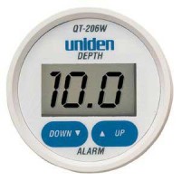
Before our July cruise, I installed the Hawkeye Depth Finder Model #D10D because my previous low-dollar depth finder (Uniden QT 206W) had failed. I’ve had a good opportunity now to compare the performance of both, and can definitely recommend the Hawkeye over the Uniden.
It seems that it is possible to pay up to $500 for a large format “sailboat” depth finder that mounts on the bulkhead. However, the availability of high-dollar stand-alone units is dropping off due to the popularity of consolidated multifunction displays for gps/chart plotter/depth finder/radar displays. And as I’ve looked at the market recently, I’ve noticed what seems to be greater selection among models and makers in the budget depth finder realm. I think makers of marine gear are understanding that the market for high-dollar gear has out priced the budget boaters, and they are now offering more products in the $100-$150 range, which is where I live as well. Don’t mistake this as altruistic behavior on the part of marine gear makers – I’m sure they are more motivated to not leave money on the table by ignoring this large group of boaters.
Regardless, the Uniden model represented a poor value with respect to construction and performance. I had this unit installed on my boat for about four years. After the first year, the display began to suffer from UV and weather-related damage, although it still functioned. The plastic display became frosty, the printed controls lost their readability, having faded in the sun. Finally, the display window cracked, which allowed moisture to enter the unit and make it unserviceable.
Performance-wise, it was inconsistent at best, but I must say that whenever I absolutely needed to know the depth when approaching shoal waters, it gave me the right information. This may in part be due to my choice of installation. I installed the transducer inside the hull without drilling a hole, and I didn’t glue it to the hull with epoxy – rather, I bedded it in a blob of silicone. I am confident this degraded its performance to some degree. It would never give much in formation in waters deeper than 50 feet, and often in choppy conditions it would return error readings, I assume due to the amount of air passing underneath its location just behind the vee-berth, or the inability of the processor to keep up with excessive motion as found in choppy conditions. When that area was ventilated by air bubbles, I feel sure the device had a more difficult time determining depth. Additionally, it featured a gain, or sensitivity adjustment on the back side, which was extraordinarily touchy.
By comparison, the Hawkeye, while still mostly plastic, features a glass screen. While vulnerable to impact damage, it is nearly impervious to effects of UV radiation, which means that the screen will always be readable. Additionally, it comes with a protective cover which will shield the unit from the sun during the many days and weeks when the typical boat is not in use. I did not install the new transducer that was included in the purchase. Instead, I determine through reading the spec sheet, that both Uniden and Hawkeye used the same frequency and wattage transducer. Not installing a transducer spared me a lot of trouble and effort with the installation. I was also curious how the unit would perform with the old transducer.
So at about the same price point (approx. $100 for each) the Hawkeye is a much better value than the Uniden. I feel more confident with this unit on board than I have with any other brand during our ownership of Cay of Sea – and early on, we had a “legacy” Datamarine large-format (read expensive) depth gauge.

Tuesday, October 20, 2015
Transforming Current
Please welcome new contributors Sean and Louise, who live aboard their 52 foot one-off steel motor vessel, m/v Odyssey. For their first contribution, Sean offers a project which provides insight into marine electrics - a subject that can never have too much light cast upon it:
I'm perpetually behind on projects here, which I think is a condition of living on a boat, or perhaps just a condition of modernity. So I've been taking the time, on otherwise idle days at anchor, to whittle away at the list. I'm also perpetually behind on blogging some of the major projects I've already done, such as the great 24-volt conversion project that I've been promising to write up for over a year now.
In an effort to keep the backlog from growing, I thought I'd use some of the time to write up one of the most recent, considering weather has pinned us down here for at least another day or so. As with so many projects, this one has been on the list for a long time, but has bubbled to the top because recent events on board increased the urgency. I am talking here about fixing the main AC panel ammeter that tells us how much power we are drawing from shore or generator systems.
The ammeter, in this case, is part of the Blue Seas AC/DC circuit breaker panel built into the helm console, which is original to the boat and has been there, according to the photo record, since it was originally finished under the first owner's watch. While large and swoopy-looking and "custom" labeled, this breaker panel is actually an off-the-shelf item available in the Blue Seas catalog. The labels come with it on a big sheet of commonly-used circuit names, for customization by the installer.
Main AC ammeter (left) and selector switch.
As such the ammeters are actually pre-installed and pre-wired on the panel. The DC ammeter is hard-wired and measures all the current passing through the main DC breaker on the panel, while the AC ammeter is wired, along with the AC voltmeter, through a built-in switch that allows it to be switched from one AC leg to the other.
This is all well and good, but in this configuration it has, as far as I can tell, never, ever been able to measure all the current the boat is drawing on either leg. That's because there are some large AC loads that do not actually pass through the panel on the helm.
When we got the boat, the big culprit in this regard was the washer/dryer. It's located in the engine room and is the only 240-volt appliance on the boat. When the automatic transfer switch (ATS) was added during the last owner's stewardship, the electricians split the feed to that appliance off right at the ATS, running it through a separate tiny panel with a two-pole breaker for the washer/dryer and another single-pole breaker that supplied the engine room exhaust fan. Any current being used by those items was thus not included in the totals shown on the helm ammeter.
The engine room fan was moved off this arrangement early on, because wired in this way it could only be operated on shore or generator power. We don't typically run the generator under way, which is exactly when we need the exhaust fan, and so I moved it to a circuit connected to the inverter.
Having the enormous load of the dryer invisible to the ammeter was problem enough in itself. We often tripped the shore power breaker when using the dryer, until we learned just how much (or little) other load we could have on the system at the same time. We had to go by feel, guessing at the amount the dryer was using at any given moment, subtracting that number from the 50-amp shore supply, and keeping everything else under the remainder based on the panel ammeter.
The problem grew much worse when I completed the aforementioned great 24-volt conversion project. That involved, among other things, a new inverter/charger, which was best wired with a 120/240-volt, four-wire circuit, thus loading both legs of the input power, in contrast to its predecessor which was a 120-volt-only, three-wire load and was supplied by a circuit on the main helm AC panel.
The "new" main panel, in the engine room, a 120/240-volt 8-space "main lug" QO-series panel. Two-pole breakers feed the inverter/charger and washer/dryer, while two single-pole breakers feed the two sides of the former main panel at the helm.
The helm panel has no provision for 240-volt circuits (it's arranged as two separate 120-volt panels), which is probably why the washer/dryer was not wired to it, and why I could not wire the new inverter/charger to it either. Moreover, wiring such a big load through the helm meant the power would pass right by the load in the engine room on its way to the helm, through the panel, and then all the way back again, adding cable, weight, heat, and voltage drop.
So now we have two of the largest consumers on the boat -- the dryer and the battery charger -- that do not register on the helm ammeter. Even with the higher 67-amp capacity of the generator circuit, we still occasionally trip a main breaker, and this problem is just getting worse now that we are running air conditioning more often. And if we want to deliberately load the generator right to its limit, to reduce wet-stacking, we have no good way to monitor our progress toward that end.
The simple answer to all of this is to move the input for the panel ammeter down to the engine room, immediately after the transfer switch, so that it can see the full draw of everything on the boat. Easily said, but a lot of work to actually do.
AC current is measured with a device known as a "current transformer" (CT). Unlike most transformers you might encounter in a typical electrical system, which transform one voltage to another, a current transformer actually transforms one current to another, proportional, current. In the case of our ammeter, it's a 1,000-to-one ratio: a 50-amp current passing through the main feed is transformed into a 50-milliamp current into the meter, while, say, a 12-amp current would result in a 12-milliamp meter input. The meter pegs at 50 milliamps, but the dial is marked from zero to 50 amps.
Physically a CT is a toroidal coil, with the current-carrying conductor to be measured passing through it. It picks up the magnitude of the measured current by induction. The CTs in the Blue Seas panel are very small, just big enough to go around a 6-gauge wire with a bit of room to spare, making them easy to fit into the tight space for which the panel is designed. That also made them ideal for installing in the tight space of our new main electrical panel in the engine room.
One of the two Blue Seas CTs, still installed in the old panel. The CTs that Blue Seas uses have their pair of lead wires molded in. Blue Seas has soldered the other ends of the leads to the selector switch. I cut the leads at about their midpoints. To extend these down to the engine room I needed about 35' or so of two-pair wire, but all I had on hand was some 4-pair CAT-5 communications cable. While I would not use untinned, coarse-strand cable like this for any critical application on a boat, for the meter it would suffice. I used two pair for each CT to minimize the resistance. At least the fine twist of CAT-5 will also minimize inductive interference in the signal.
CT relocated to new main panel in the engine room. The zip tie just keeps it from sliding on the wire.
After moving the CTs and splicing the wiring at each end, we fired up the genny for a test. While I was concerned that such a long run of meter wiring might impact the accuracy, a quick check with my clamp-on meter revealed that the helm meter is spot-on. We now have an accurate reading of the full draw on both legs up to a maximium of 50 amps, which is the limit when we are on shore power.
The generator is a 16kW unit, however, which means it is theoretically capable of producing 67 amps, and in practice has a 70-amp main breaker. Consequently, when running on the generator the 50-amp ammeter can and does peg occasionally, particularly on the leg carrying the battery charger, which by itself can draw up to 30 amps. For the time being, we avoid leaving the meter connected when running above 50 amps (the selector switch has an "off" position).
I'm not too worried about running the CTs at 30% above their 50-mA rating, as these are minute amounts of current. But the meter itself could be damaged long-term, and besides, we'd like to know exactly how much we are drawing even when we go above 50 amps. So I will probably devise a shunt that can be switched in when on the generator to divide the reading in half. I'll need to experiment to determine the meter's internal resistance in order to size the shunt.
We almost never trip breakers when running on the generator, which is large enough to run almost everything on the boat simultaneously unless we are running the dryer, which we try to run mostly on shore power anyway. So the meter is most useful in managing the more limited shore power feed, and for that, the 50-amp full-scale reading is perfect.


Tuesday, October 13, 2015
How To Make Holes In Your Boat
Making a hole in your hull is serious business, even more so if your hull is foam-cored. Jeff and Anne aboard s/v Pilgrim and in the midst of a complete refit demonstrate how it should be done...
We have added two new 1-1/2” thru-hulls above the water line. The port thru-hull will serve as the discharge for the upper, larger capacity bilge pump (3700 G/H).
The starboard side thru hull will act as a drain for the deck scupper. We did not like the long hose run from the starboard scupper to the torpedo tube drain manifold. We also wanted to rig a method for collecting water off the deck if necessary.
Prior to drilling any holes we assembled the new starboard deck drain plumbing.
Test fit of new plumbing for starboard deck drain. Note old drain hose at far right. Test fitting the new plumbing allowed us to accurately mark the location for the starboard thru hull. The port side fitting connects to a single flexible hose so identifying the exact location was less critical.
Since the location of the holes was marked on the inside of the hull, I began the drilling using a ¼” bit to drill a pilot hole from the inside out. The ¼” hole matches the diameter of the hole saw pilot bit. Next, I chucked a 1-7/8” hole saw into the drill and moved outside the hull. Drilling the larger hole from outside allows for properly aligning the hole perpendicular to the hull and creates less dust inside the boat.
We drilled two 1-7/8" holes in the hull. The Morgan 382, 383, & 384 hull’s have a foam core above the waterline. This is the first time we have drilled large diameter holes above the waterline and subsequently our first look at the coring material.
Close up of plug offers a glimpse of Morgan's construction techniques. The hull is slightly over one inch thick… the outer fiberglass layer is 5/16”; the foam 9/16”; and the inner fiberglass layer 1/8”Placing holes in cored hull’s or decks requires additional effort to ensure water never reaches the core material. In smaller, fastener sized, holes this can be achieved by over drilling the size of the hole and then filling it back with epoxy. Larger holes for plumbing fixtures require a different approach.
Using a small flat screw driver and a couple different styles of picks, we removed all the coring material within approximately ½” of the hole.
Foam core removed from the area around the hole. The plan is to fill the newly created void around the hole with thickened epoxy. So the next couple steps are the usual epoxy prep… 80 grit sanding, acetone wipe down, mask area... We used a syringe to apply the epoxy and a plastic spreader to achieve a nice clean finish.
Filling the area around the hole with thickened epoxy. After a couple days for the epoxy to fully cure, we returned to the project. Using a #49 cabinet rasp and some 80 grit sand paper, Anne cleaned up any excess epoxy from the holes. While I cut down the length of the threaded section of the thru-hull to properly fit the valve on the starboard side.
Prior to applying any sealant we dry fit the two thru-hulls and masked the surrounding area. For the final install we used 3M 5200 sealant. Anne worked the interior and I the exterior.
New thru hull fittings are just above the waterline and five feet forward of the torpedo tube drain on either side of the hull. We are still waiting on hose to connect the bilge pump to the new fitting on port, but we wasted no time installing the new starboard deck drain plumbing.
New deck drain w/ option for filling water jugs installed. Since the installation we have weathered a couple heavy rains. The starboard deck scupper is performing much better with the new system.
What was that you said?
Why yes that is a new battery selector and bilge pump switch panel in the image above. I’ll post more info on that project very soon.


Subscribe to:
Posts (Atom)


