I will be on vacation and out of Internet coverage for a week. I hope you can forgive me for the resulting hiatus in this blog...
bob
s/v Eolian
Seattle
Tuesday, July 30, 2013
Thursday, July 25, 2013
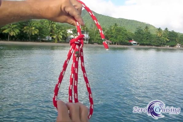
The King of Knots
Do you know how to tie a bowline?
Good. How many ways? Oh, there is more than one way? Yes indeedy, and Mike on s/v Zero to Cruising (aka s/v ZTC) shows us several ways. One that you should definitely learn is how to tie one around your body - you never know when you might have to do this while being drug astern...
Good. How many ways? Oh, there is more than one way? Yes indeedy, and Mike on s/v Zero to Cruising (aka s/v ZTC) shows us several ways. One that you should definitely learn is how to tie one around your body - you never know when you might have to do this while being drug astern...
“The first lesson a yachtsman should learn is to join the ropes together, sailor fashion.” VanderdeckenThe classic bowline a must-know knot for all mariners. The following video demonstrates both the basic version and multiple others. We find that we use the slipknot version shown in the video much more often than we do the basic one. How many of these variations were you familiar with and even more importantly, will you take it upon yourself to grab a piece of line and work through the ones that you didn’t know?
Notes:
- Rabbit and Tree: How most people are taught the bowline. Make sure you can do it around an object and also both facing towards you and away from you. Many people get mixed up with that.
- Slipknot. Very fast. Experience will tell you how long you need to leave the tail. This is a good method to use when you want to have it ready to go to make fast to something that will be under load (a sail, a mooring ball pennant, etc.).
- Enhanced, Double and Water: These three versions all add additional friction. A bowline is a good knot but if unloaded, it can come loose, especially when in the water. These versions lessen the chance of that happening.
- Bowline on a Bight and Portuguese Bowline: Both of these create double loops which could be improvised as a bosun’s seat. Note that the loops in the Portuguese version are not fixed. If you pull on one it will slide making the other loop smaller. This will not occur on the Bight version.
- Around your body: Good if someone throws you a line when you’re in the water. Better practice it on land first though!
Tuesday, July 23, 2013
New Bilge Pump & Strainer
Petr and Jana on s/v Janna came up with a nifty solution for a bilge pump strainer for their new bilge pump...
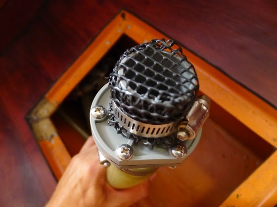
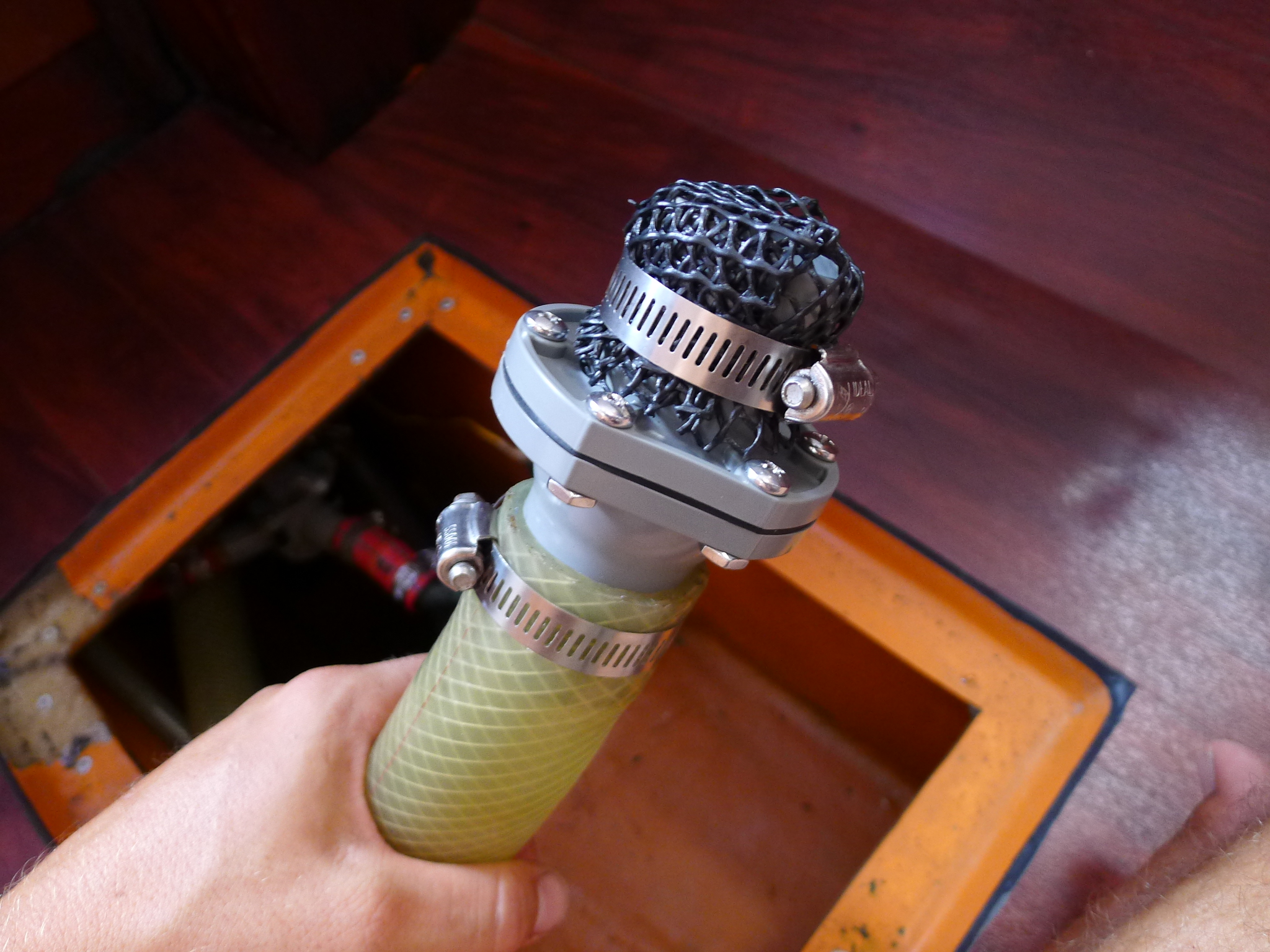
We naturally love water, but same as with the fire, it is a good servant, but a bad boss. Recently we found out that our otherwise quite dependent bilge pump Rule 1100 started malfunctioning. First the float switch started to get stuck and refused to get lifted by the water in the bilge. Soon the motor would start working only sporadically and when it did work, it wouldn’t have enough power to lift the water.
I tried to get inside, but the motor is sealed in a plastic body of the pump, so we decided to order a new one, which is by the way, quite improved, the float is hidden so it cannot get dirty and stuck. At the same time we ordered an inline check-valve for our manual bilge pump Gusher 10. We were looking for a similar strainer that we had before, but the advantage of the strainer, other than being able to be attached to the floor, is not so clear to me, so I just attached a piece of strong plastic netting on the check-valve to get a cheap strainer. The netting is naturally important to prevent hard large objects getting into the bilge pump and puncturing the membrane.
Now everything is back in working order and we sleep a tad sounder, i.e. until there’s water in the bilge which triggers an annoyingly alarming buzzer…

Thursday, July 18, 2013
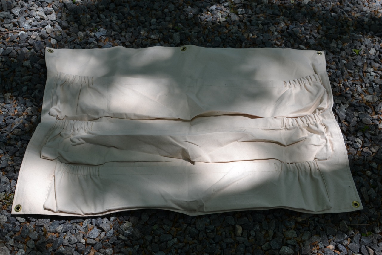
Hatch Board Storage – Project Complete
Hatch boards (AKA 'wash boards') are a pain. They are large and heavy - dangerous potential projectiles in a seaway. Very few boat manufacturers provided storage for them when they are not in use in the companionway. But over on s/v Cay of Sea, Rick has finished his hatch board storage project - here is one way to address the manufacturer's shortcoming...
In January I showcased the drop board storage my talented wife sewed and gave me for Christmas. Now five months later, I have finished the installation, and it works perfectly. I am so pleased with how this turned out, and how convenient it has made stowing the boards. They occupy almost no extra room when stowed, are easy to stow, and easy to retrieve.
All the sewing and needle work was finished for Christmas, but the pockets still needed a location and mounting system, as I detailed in the previous post. To that end, yesterday I fitted brass grommets (3/8″) to each corner, plus an extra grommet in the top middle to prevent sagging.
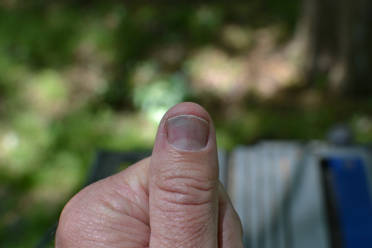
That paragraph makes it sound easy, and truthfully, it wasn’t really difficult. What was difficult was learning that I have to hold the grommet tools in place with vice grips, because it really hurts when, holding the tools between thumb and forefinger, I smash my thumb while using the cutting tool. But on a philosophical note, this little injury has served to remind me that “it’s not a boat project if I don’t experience pain somewhere. . .” The other thing that really hurts about this, is knowing that I’ve done this before. Sigh. . . it’s difficult being me.
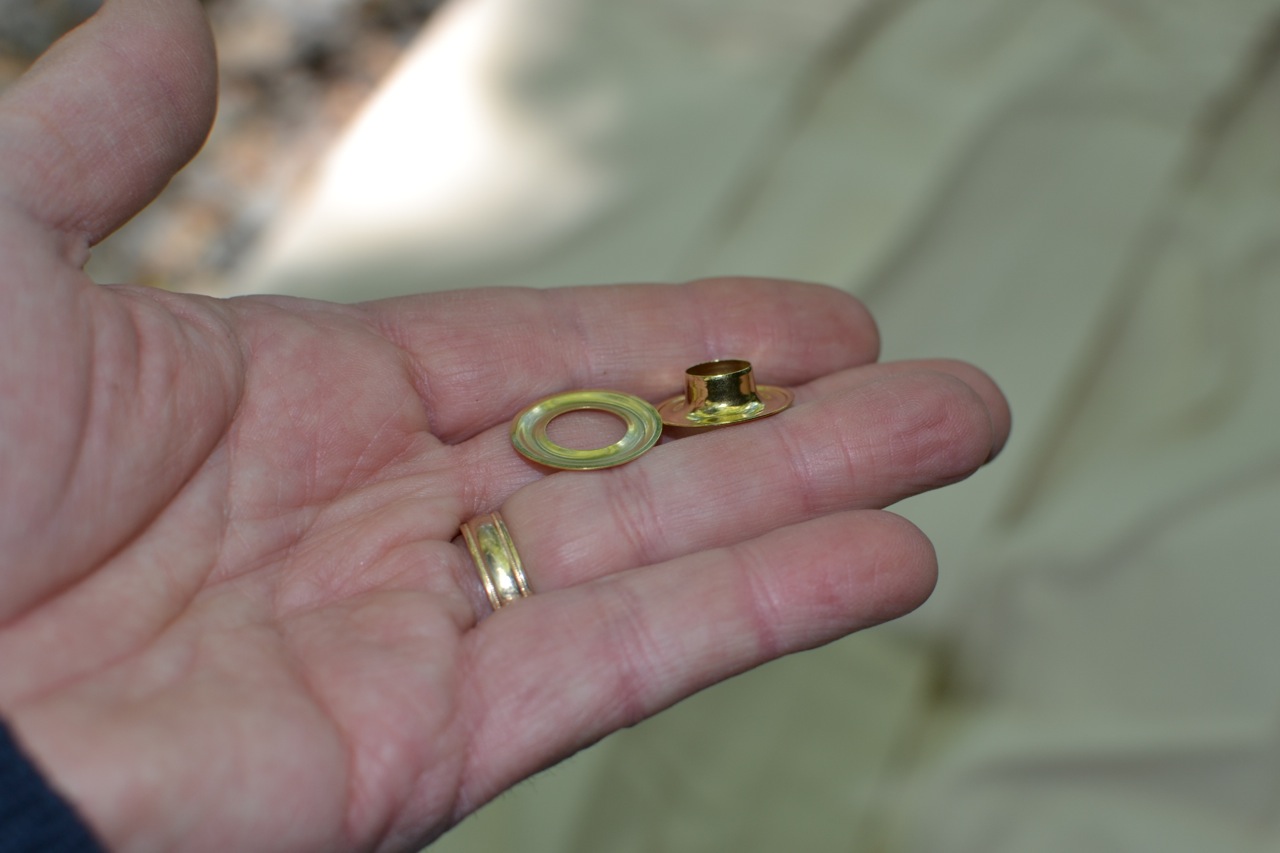
So how does this work? The grommet kit comes with the two-part grommets, a material cutter, and setting tools, as shown below:
Two-part grommet.
Cutting tool. This end is sharp.
Base for setting the grommets. The piece with
the flange sets on top of this, flange side up.
This is the other half of the setting tool. It sets
on top of the grommet collar and is driven
through the material and grommet halves.
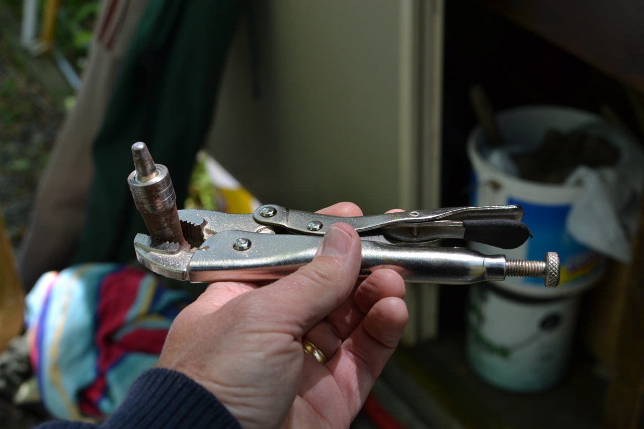
The shape of the tool clamps the grommet halves
together. Note that I have clamped it into vice-grips
for safety.
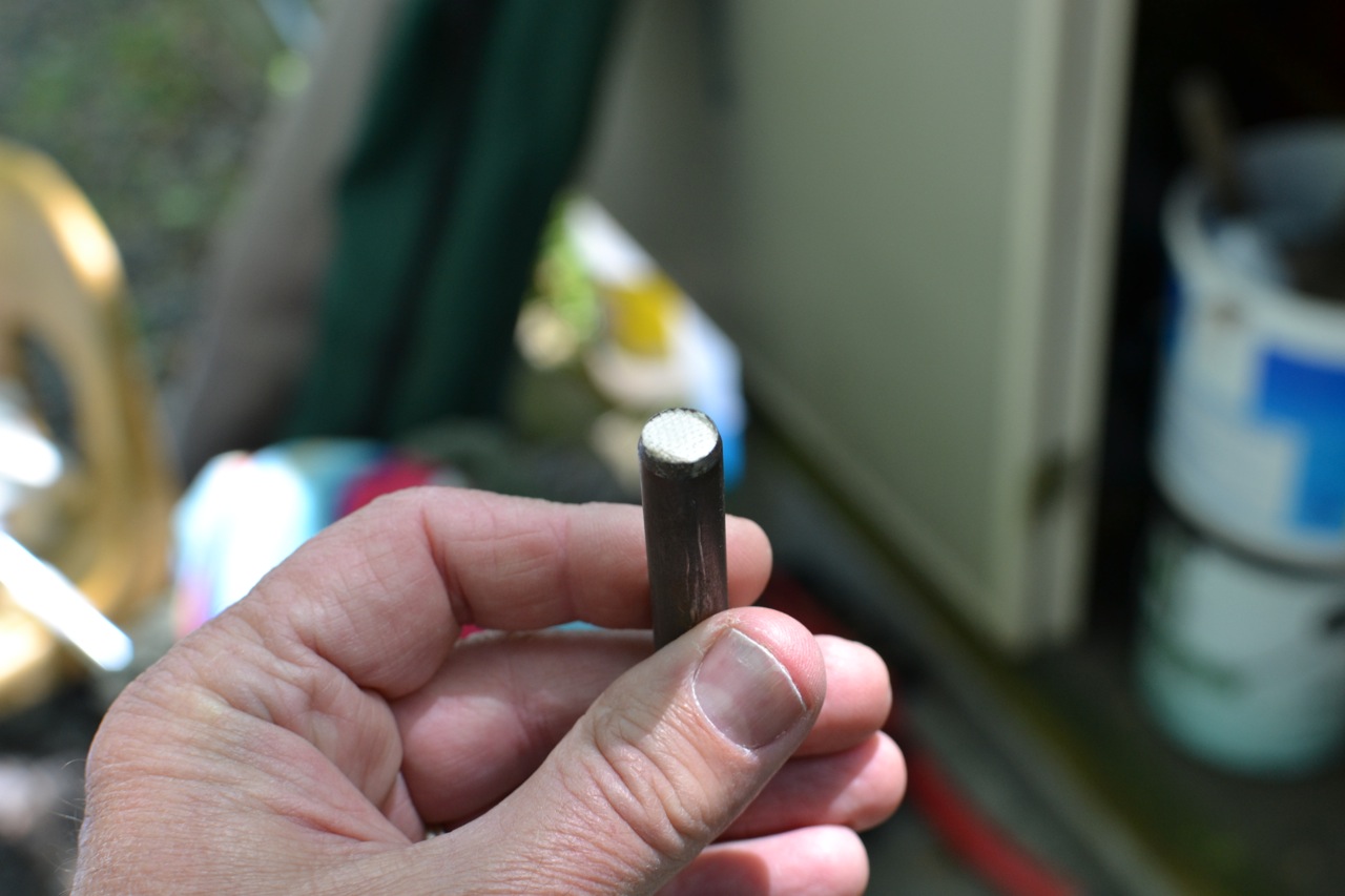
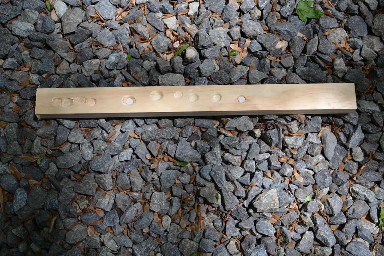
Using a wood backing board, set the cutter into the area of material where a grommet is desired. The backing board must rest on a surface that has no bounce or give. Then using a hammer, drive the cutting tool through the material (and usually the backing board too) to cut a perfectly round-shaped hole.
Here’s the backing board I used.
Set the material on it and drive the cutting tool
through the material. Watch out for your fingers!
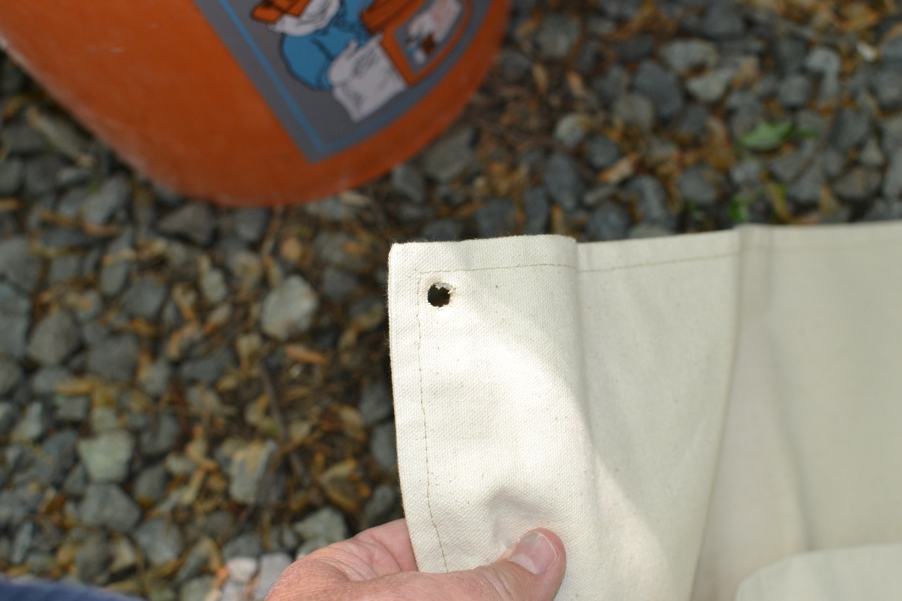
Perfectly round hole.
I have done this with knives, scissors, and red-hot
implements, but this thing gives a perfectly shaped
hole each time.
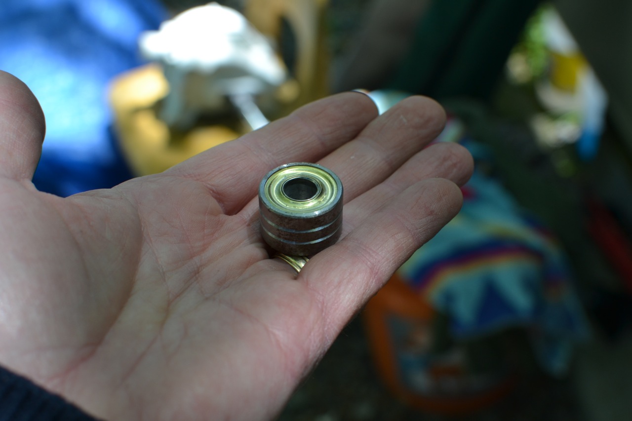
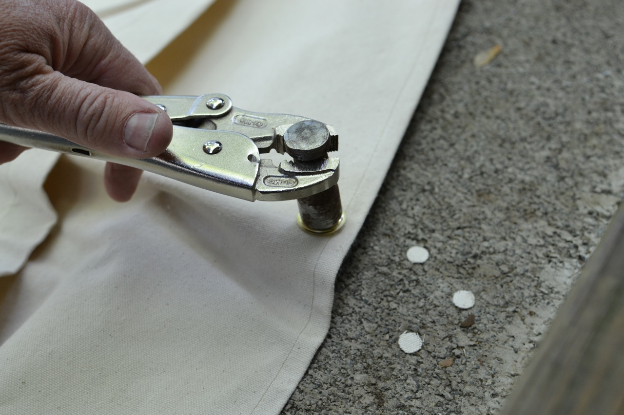
Now set the base on the solid surface, place the grommet half with the flange on top of the base (flange facing up) and place the recently cut hole over the flange. Now place the ring half of the grommet over the flange (on top of the material). Place the setting tool inside the flange and drive it down with a hammer (again, watch your fingers).
Base on bottom; flange half on base; hole over flange;
ring half on top of material (over flange); setting tool
into flange and drive down with 3-5 good whacks.
See the vice-grips? I’m getting smarter.
Pain promotes learning.
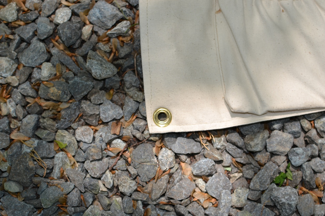
The result is a brass-reinforced hole.
This grommet took about 90 seconds to install from
start to finish – not including thumb injury and
time out for ice treatment.
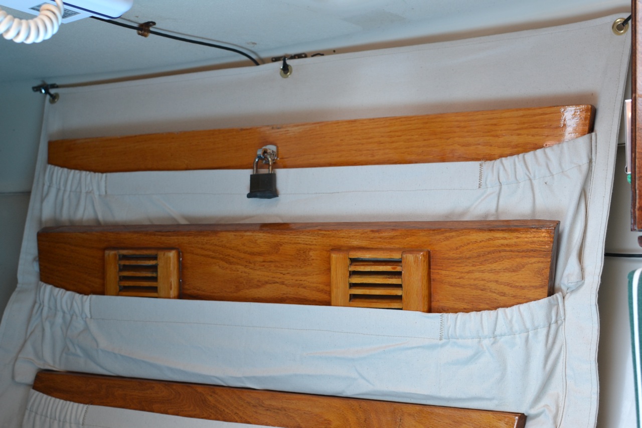
On the boat, I installed strap eyes on the outboard side of the quarter berth: three top, two bottom. I set them to pull the top pretty tight, and attached the pockets with zip ties. This was fast and easily adjustable.
Sorry about the shadows.
Mounted at top.
Strap eye and zip tie.
Secure at the bottom. On a port tack in choppy
conditions, if not secured, the bottom could
bang around as it fell away from the hull.
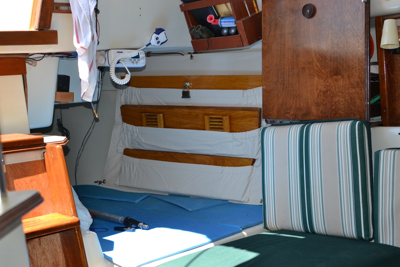
Final photo.
This has really un-jumbled the quarter berth and
solved the question of where to put these things.


Tuesday, July 16, 2013
Running Wires for Solar Panels & Wifi Antenna
Last week, we featured Jeff and Anne's installation of new solar panels on their boat. Now that the panels are installed, they still need to be wired into s/v C'est la Vie's electrical system...
Pulling wires though small openings and running wires along tubes pretty much describes my afternoon Wires from the new solar panels now snake over the bimini, along the stern rails, and thorough the deck via a new through deck fitting installed starboard side aft.[Editor's note: C'est la Vie was dismasted on July 5 off the Frying Pan Shoals. Jeff and Anne are fine, and C'est la Vie was able to motor under her own power to a safe harbor, where whe is currently hauled out. You can read more about this here, here, here, and here. There are some important lessons to be learned from this - I encourage you to read Jeff's account of the event.]
We purchased a WirieAP which serves as a wifi antenna and creates a wireless network for the boat. Our decision to go with the Wirie was based on a Practical Sailor review and additional internet research. I must admit the the fact that the creators of the device and owners of the company are live aboard sailors won them some favor as well.
One #10 wire from each panel now runs down along
the starboard stern railing and through the deck.
The unit is self contained in a waterproof box. The only cabling is a wire for power. The unit is sold as a 12V DC system, but a 120V AC adapter is included in the box. The unit also includes a mounting bracket for 1" to 2" poles. Experimenting with different installations on C'est la Vie, we elected to bolt it through the angle brace on the wind generator tower. This does place the antenna close to the pole, but once again life of a sailboat is a series of compromises (or is that true of life in general?)
the new WireAP mounted on the
stern wind generator tower
With the antenna mounted, I returned to running wires. Fortunately a through hull fitting already existed for the Wirie cables.
Pulling all the wires below decks forced me to excavate the contents of both the lazurette and the starboard side cockpit locker.
The cockpit quickly became an obstacle course / work area.
work zone or obstacle course?
As light began to fade from the sky and the hungry Everglades bugs began to take over, both the wifi & solar wires run into the starboard side cockpit locker. Hopefully tomorrow I can complete their journey to C'est la Vie's electrical panel.


Friday, July 12, 2013
The right dipstick?
Mike and Rebecca of s/v Zero to Cruising are soon to move aboard a much larger boat - a Leopard 4600. This boat has a pair of diesel engines equipped with SD50 saildrives...
I’m sure it can be said that all engines have their own issues. Our last few years have been spent learning the ins and outs of outboard engines. While that info is still important as we will have a Yamaha outboard powering our tender, the Leopard that we’ll be living and working on has an entirely different setup for its auxiliary engines.
In the stern of each hull of the 4600 lies a 54HP Yanmar diesel engine. Unlike some of this boat’s Leopard predecessors, the engine is not connected directly to the propellor via a straight shaft. On the contrary, it transfers power through a couple of right angles via a system called a saildrive. On the 4600, the particular model of saildrive is a SD50, a piece of gear not unknown to have issues.
A SD50 saildrive
I have had the good fortune to be exposed to some of these issues because our friends Kirk and Donna have the exact same engines and saildrives on their Lagoon catamaran, Ainulindale. I have witnessed first hand some of their woes and the steps that they have had to take to rectify them. One particular issue relates to leaking seals on the saildrive, quite possibly the result of overfilling the gear oil chamber. How could that possibly happen? Quite easily actually.
It seems that most of the SD50s out there have a dipstick with incorrect markings for the high and low gear oil levels. While this info was made known to the dealers via a service bulletin, I’m not so sure it has filtered down to all of the users. Fortunately for us, Kirk did find out about this. The photo below is of the new, properly-marked gear oil dipsticks. Each one costs less than $10.00 and having them can help to avoid seriously costly engine drama. Big thanks to our buddy Kirk for sharing this info and for picking us up two of the dipsticks for the new boat.
The new properly-marked dipsticks.
If you have an SD50, you might want to look into this. I have been told that the new dipsticks are all marked with a dot on the top made by a back sharpie marker. If your dipsticks are missing that dot, you might want to follow up on this.


Tuesday, July 9, 2013
Holding Tank Modifications using Polyethylene Pipe
Paul on s/v Solace tackles one of the more unpleasant tasks on a boat - head/holding tank plumbing.
More work to my holding tanks! I alluded to some of the benefits of using polyethylene hose for sanitation hose and you can read about it here.[Ed. Note: Solid PVC plumbing pipe (like used in your house) is also recommended as a permanently non-permeating alternative to the garbage sold as "head hose"]
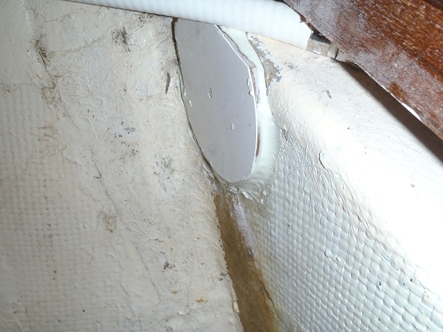
The first thing I did was remove the input hose and fitting, to the holding tank which was located on the side of the tank. Last year, I had relocated the tank air vent to the top and did a temporary block off, of the old side air vent. You can read about that here. That was located just above and to the side of this fitting seen to the left. I used a Dremel and hacksaw to make the cut of the bronze fitting.
I prepped the area to get ready to epoxy glue on a cover over the old fittings. Old paint removed and each opening stuffed with toilet paper so that the glue would not full into the tank. The glue is made from two pot epoxy (slow set) with silica powder/binder added until you get the consistency of thick peanut butter.
To the left is the finished fibreglass plate epoxied to the tank. This year I decided to use some off cuts of fibreglass which are cut out when the boats are removed from the molds. Typically, they are window cutouts and hatch cutouts which are then discarded. You local fibreglass boat builder will have plenty of these to give away.
In preparation for the top fitting, I found the best location; drilled my hole for the polyethylene through hole; and then sanded the area for gluing the fibreglass plate to the tank.
To the left is the finished fitting. You might notice that the black hose it is attached to is polyethylene pipe.
Polyethylene pipe is NOT as flexible as sanitation hose, so you may have to use elbows etc to get it to go where you want to. You can also use boiling water to get a little more curve from the pipe.
To the right you can see the 25mm polyethylene pipe running down and through the wall where it goes to the macerator pump. The bigger 38mm (inch and a half) pipe runs from the bottom of the tank to the "Y" valve and then the polyethylene pipe continues on to the pump out pump. A diaphragm pump with joker valves each end.
Now the outflow is of poor design and should never come from the bottom of the tank, other than a drop down pipe inside the tank, from the top. This is due to the fact that effluent is always in the outflow pipe which leads to permeation I'm using polyethylene pipe from the bottom of the tank and feel confident, there will be no permeation.
Above you can see I used barrel nuts. This makes presenting pipes up to the fittings real easy. In this case I didn't need to use them, but I had bought them with me, so decided to use them.
To the left you can see the macerator pump with barrel nut fittings at both the inlet and outlet. The outlet has a PVC type which was fitted some time ago. On the other side of the barrel nut, I have a joker valve inside the other half of the PVC barrel nut and then a valve. This is because it is pumping up hill and one day I may need to service.
I have now added a polyethylene barrel nut at the inlet side. Also, but not shown, is a threaded pipe (at the inlet side before the barrel nut), which goes to a valve, before joining up with the 38mm pipe from the toilet bowel. IF the pump needs servicing, I just turn off the valves at either side of the pump; undo the barrel nuts (usually by hand); disconnect power; and pull the pump out. I have a few "boat towels" to mop up the small amount of fluid that will spill.
And let me say, the area smells so much better already. I might even replace the deck pump out hose ( which goes to the "Y" valve. But my wife says, that is just looking for work. Maybe if I get bored sailing?
Listening to "Just Waiting on a Friend" by the Rolling Stones.


Tuesday, July 2, 2013
Solar Panel Installation
Cruising boats and solar panels just go together. But the way they get mounted is as individual as the cruisers themselves. Here we see how Jeff and Anne addressed the mounting on s/v C'est la Vie. Also, please note that the hard bimini top that they installed in 2010 gets replaced as a part of this prioject.
The addition of a photo-voltaic (PV) system to C'est la Vie has long resided on our wish list. Thanks to Ben V., an friend and co-worker who's previous profession was solar installations, for providing the expertise to jump start this project. We ordered two Sunmodule 80W panels and a BlueSky Solar Boost 2000E charge controller from altE. The size of the panels was a compromise between energy production and mounting space. I'm certain many cruisers are faced with the same dilemma... want / need bigger panels, but lack suitable mounting options.
The equipment arrived in early March.
About a month ago I installed the BlueSky Charge Controller in the electrical panel.
BlueSky Charge controller is on the upper right of image
Then progress on the PV system installation took a back seat to painting and the cabin sole refinishing. With the painting & refinishing projects nearly astern, we are now directing our efforts back to PV system. Next step... mounting the two panels.
Our original FRP Bimini, installed in June 2010 (see Fitting Day For the New Bimini) held up well, but was beginning to show it's age... one ripped back corner the result of an accidental jibe and a couple cracks along fittings at the gallows. All told we are very pleased with the performance of the FRP and elected to replace the bimini with a new sheet, $38 for a 4' x 8' piece at Lowes. Experience taught us the best way to cut the material is with a fine tooth circular saw for long straight cuts, a hole saw for circles, and a dremel tool with cut off blade for short precise cuts or broad arcs.
We used the old bimini as a template for the new. Once the centerline of the new bimini was secured to the frame via conduit clamps (see image below), we placed the solar panel on top and debated the best options for mounting.
The new bimini quickly took on a swiss cheese
look as we cut out access points for the solar panel installation
We decided to screw the forward panel frame directly to the wooden gallows. The rear section of the panel is attached directly to the bimini frame via two conduit clamps. The FRP bimini is also attached directly to the solar panel frame via machine screws & nuts along the leading edge. Facilitating access to all the fasteners required five cut outs on each side of the bimini.
Port side bimini & panel installation from below.
From below the only noticeable difference are the cut-outs and the addition of two conduit clamps along the rear frame. One pair of 10ga wires for each panel will exit the bimini and snake down to a through deck fitting, but that is tomorrow's project.
From above the panels' only shade will come from the mainsail. Unfortunately the panels are not adjustable to track the sun, but outfitting a cruising boat is all about compromises.
The view from above. The only shade will come from the mainsail.
From afar the panels are relatively obscure and do not add clutter to C'est la Vie's profile.
The starboard panel from afar.
The installation adds little windage or profile
clutter beyond already existed from gallows and bimini.
The panels will add to the difficulty to securing the mainsail boot. Due largely to the boom gallows and the cut of our new mainsail, I do not feel the panels will be in any danger from the main sail hardware or sheet.
We created a photo album to document the PV project... Solar Power - Spring 2013


Subscribe to:
Posts (Atom)


