Tuesday, May 26, 2015

I wonder if you knew


This post is a mash-up of two posts that originally appeared on Windborne in Puget Sound

Say you have a boat, and say that the gelcoat has some flaws in it (but then I repeat myself).  These might be caused by say, a dock that approached too quickly, or perhaps a wayward buoy inconveniently located right on your waypoint.  Never fear... you don't have to live with those flaws.

Gelcoat is simply polyester resin with pigment and some flow modifiers added to it - there is nothing magic in it.  The magic *is*, however, in getting the right mix of pigments so that it matches the gelcoat on your boat.  You can do this (I have), but it is a truly tedious process and, for me anyway, very very challenging.  Instead, I have an alternative for you.

I wonder if you knew that Fiberlay will make up a quart (minimum size) of gelcoat to match your sample.  They scan the sample using not one, but three different light sources, take the average of those three results, and use that as a starting point for a manual match.  You even get a custom label!

(Pay no attention to the gelcoat smeared on the outside of the can, and don't let the can fall out of your car onto the pavement - the lid will probably come off)
The cost is surprisingly reasonable:  $73 tax included.  That compares to a quart of off-the-shelf Interlux Brightsides urethane paint which pushes $50 pretty hard.  Not bad at all.

Now, here's the tricky part - how do you get them a sample to scan?  If you have something that can be taken off your boat that has representative gelcoat on it (a lazarette hatch for example), then you are in good shape.  If not, then I hope you have saved all those plugs you cut out when installing instruments, etc. 
Always save those plugs
But even failing that, for an additional charge, Fiberlay will send a technician to your boat to do the scan - but I expect that the additional charge is not necessarily trivial, skilled labor being the most expensive commodity in today's world.

Next, you will have a choice to have the gelcoat mixed up with or without wax.

Wax?  Why wax?

You see, oxygen is a chain stopper for the polymerization reaction  that turns liquid polyester resin into solid polyester resin.  That means that the surface of a gelcoat application will not cure where it is exposed to air.  When you are making a boat in a female mold, this is a good thing, insuring that the next layer to be applied will bond chemically with the uncured surface of the gelcoat.  When patching this can be handy too, especially since gelcoat shrinks some while curing, and thus will likely require more than one application to a given patch.

PVA
But eventually, you will want the final layer to cure.  That's where the wax comes in.  If the gelcoat has wax mixed into it, the wax migrates to the surface as the cure progresses, sealing off the surface from the air and making a complete cure.  This is what you would want if, for example, you were spraying gelcoat onto a finished lamination on a male mold.  Or if you were willing to scrupulously dewax the surface before applying another layer of gelcoat.

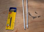
I chose to have the wax left out.  And I bought a small bottle of PVA (polyvinyl alcohol).  This is a water soluble plastic that can be painted over the final layer of gelcoat to exclude air from the surface.  A simple water rinse removes it.


So, how did it turn out?  Here you go:


Filling some screw holes and chips on the edge of a cockpit seat
Looks pretty good, doesn't it?  I must say that managing the gelcoat as you are applying it is difficult.  Just like working with polysulphide, it seems to get on everything, including my hands, my pants, and my feet.  You will want to keep a can of acetone and a rag handy. 


Before I applied it to the problem areas, I used my Dremel tool to clean them up.  Some were just small screw holes or chips as in the picture above, but one area needed severe remedial work.  I mixed the gelcoat in a plastic cup with a tongue depressor and then used the tongue depressor to apply it.  On the next batch I think I will try a paint brush for the larger areas - the stuff is pretty runny.

After it goes off, it needs to be sanded, a process I am way too familiar with from doing automotive body work.  I used 220 grit wet/dry paper, wet, and I applied blue tape around the area to be sanded so that I wouldn't accidentally sand thru the gelcoat on adjacent areas.  Once I had the patch down to about the thickness of the tape I switched to 400 grit, removed the tape, and sanded it flat.  Then a touch of polishing with some compound, and...

Poof!  Gone!
Yes, there is a little bit of white showing on the edge chip where I failed to remove enough of the Previous Owner's MarineTex patch.  I will grind it out and apply more gelcoat.  Again, a process I am way too familiar with...

But the color match is absolutely perfect!  Huge kudos to Fiberlay for a match well made!

Tuesday, May 19, 2015

Steaming Lamp/Deck Lamp Guard

Over aboard s/v Cay of Sea, Rick avoids paying the marine tax by fabricating his own guard for his steaming lamp:
Okay, I’ll admit that I don’t know exactly what to call this thing, but I know what I want it to do – what I hope it will do, if it is robust enough to do so. First, some background:

Two years ago my deck lamp was knocked out of the fixture, including the lens (I think), by an errant halyard slap in high winds. Well, that wouldn’t be too bad, except that I had just replaced it. It’s one of those two-pronged halogen 20 watt lamps, and they are sort of pricey. Not only that, but I hate going up the mast. Now I’d have to do it again! There has to be a better system. I imagined at the point, that some sort of cage of rods would be an adequate protection against another halyard slap. I’ve seen them on other boats, but I’ve never seen one advertised for sale, so I have no idea of availability or price. But how hard can it be to make something like that? While the mast is still horizontal and I have time before launch, I thought I would give it a try. I should be able to come up with something.

I went to the hardware store today to look for materials, and came home with 36″ of 1/8″ aluminum rod, eight stainless #6 screws, and a drill bit and tap for #6 screws.

Back in the shop I cut the rod in half and flattened the ends of the two pieces with a 3-pound maul against my closed vice, then drilled holes in the ends for the screws. I used a mill file to clean up the sharp edges.


Back at the boat, I estimated the lengths, attachments points, and the approximate locations of the bends. Without a vice on site, I found convenient places to capture one end of the rod while bending the appropriate place against a leverage point. This is what I came up with:

I managed to get one leg of the smaller piece longer than the other.  Doesn't really make a difference.  It attached to the mast without complication.
I managed to get one leg of the smaller piece longer than the other. Doesn’t really make a difference. It attached to the mast without complication, but it does bother me that the legs are not exactly the same length. . . 

I located the larger piece on the mast first and marked the attachment points. Using a steel punch, I made a small divot point in the mast at each screw hole location to get a clean start with the drill bit. Carefully locating the drill bit, I used significant pressure and slow speed to start the hole (the mast is a curved section, remember? Hard to drill a hole in something like that without having the bit walk all over the place). Each hole started and finished cleanly. I cut threads into each hole with the tap, then ran a screw into it to ensure clean threads. If you never tapped a hole, it’s an interesting process. Everything is extremely low tech, except for the tap itself – which is hardened steel, tapered at the point, with the cutting threads beginning immediately. I use a small adjustable wrench to turn the tap a quarter turn at a time as I guide it into the hole as perfectly perpendicular as possible. It’s helpful to back the tap out a quarter turn after every complete turn or so, to clean the metal debris from the cutting threads.

I marked, drilled, and tapped for the second (port-starboard) piece next, then mounted both pieces with screws well bedded in TefGel. TefGel is a non-conductive corrosion inhibitor, and it allows me to use stainless fasteners into an aluminum mast without threat of galvanic corrosion. Every place I’ve used it on the mast has been completely corrosion-free since I refit the mast eight years ago.

In case you’re wondering, sheet metal screws, or self-tapping screws are an inappropriate fastener for this application. In fact, anything screwed into the mast should be done with machine screws. They have much finer thread than self-tapping screws, and hold much more securely. I like what Don Casey says about sheet metal screws in a mast: “I’ve never seen a sheet metal mast . . . ”

Point taken.

After fitting both pieces, I linked them with a zip tie, reasoning that having them linked together would give them a bit more rigidity (4 attachment points, vs 2).

Here’s the finished product:

DSC_4333
DSC_4334
DSC_4335

Nice rounded features should allow halyards to slide right off and past the light. Cost? About $10, including the drill bit/tap set. We’ll see if it does what I hope it will. Although the rod is quite bend-resistant, the fasteners could be the weak point. As long as they don’t get wobbly, I think it will be fine. They are torqued as tight a I dare and seem quite sturdy, although it may be smart to install lock washers under the fastener heads. Any opinions out there about this?

Tuesday, May 12, 2015

Molding A Semi-Circular Fiberglass Conduit

Aboard s/v Pilgrim, Jeff and Anne continue what can only be classed as a keel-up rebuild. Most of what they are doing is not of a scale suitable to be included here (tho I have fudged a couple of times...).  But this piece of work is. 

And I did not know that about duct tape - thanks Jeff!
When constructing the 25" long conduit running under the ice box ( see – January 17th Post) I used prefabricated, 1” thick foam core paneling.  The paneling provided additional insulation under the box and the completed assembly added structurally to the hull by serving as a stringer between two transverse bulkheads.

The 5” long section of conduit running between the aft panel of the ice box and the new cockpit locker bulkhead does not need to provide additional insulation nor contribute structurally.  It’s sole function is to provide a water tight passage way under the ice box insulation.  Thus I chose a quicker and less costly method for building a conduit… 

Save for some two-part epoxy all the components of the conduit fabrication are pictured
Using a plastic, 1G jug and some duct tape I created a fiberglass mold for the section of conduit required.

The duct tape serves as a mold release agent and as part of the mold.
I began by cutting the  jug in half.  To assist in maintaining the shape of the plastic ran one strip of tape across the open face of the jug.  I then placed the jug on a board covered with plastic sheeting and covered it with duct tape.  Epoxy will not bond to duct tape so it serves in place of mold release wax.  The duct tape also allowed me to create a nice radius at the intersection of the jug and the base.

Test fitting the 1708 cloth on the mold.
I then cut a section of 1708 cloth to cover the mold.  One layer of cloth was adequate for my application, but additional layers could be added to create a load bearing conduit.

Time to walk away and let the epoxy cure.
I then wet out the cloth and laid it over the mold and went home for the night.

Conduit fresh off the mold.
The next morning I lifted the conduit off the mold.   While wearing leather gloves I dressed the sharp, jagged edges by hand sanding with 35 grit paper then sanded the entire piece with 80 grit sandpaper.

fitting the conduit to the hull and bulkhead.
I fit the piece in position and marked the excess material.  The single layer of cloth cut easily with a jig saw with a metal cutting blade.  I believe that tin snips would also work for shaping the piece.  Fine tuning the fit was done using 80 grit paper on an orbital sander.

Conduit bonded to hull and bulkhead with thickened epoxy and cloth tabbing.
Once satisfied with the fit, I used two small sections of fiberglass cloth to tab the base flanges to the hull.  I sealed the fore and aft ends of the conduit to the adjacent bulkheads with a fillet of thickened epoxy.
Now it is time to bury the conduit under layers of ice box insulation.

More images and notes from this on-going project are available in the Ice Box Rebuild Photo Album.

Tuesday, May 5, 2015

New Spreaders For The Mizzen

[Sorry about the re-post of this one. I just opened it to look at something, and Blogger turned it back into a draft. ??!?]

This post originally appeared on Windborne in Puget Sound

Rot.
It's funny, isn't it - how something like this can prey on your mind - kind of subconsciously, but still gnawing away just below the surface.  Just like the rot - slow  but relentless.

Yes, I've known about the rot in our mizzen spreaders for a while now.  And I have been intending to deal with it for all that time, but the "right" time hadn't occurred - until now.

So I tied off the mizzen halyard to act as an auxiliary cap shroud and climbed the mast with my tools.  Removal of the spreader was far easier than my worries had been leading me to anticipate, even tho it had been up there for 37 years, untouched and uncomplaining.

More rot at the root.
I had decided that the replacement spar would be made from  pressure treated lumber (like the second-generation bowsprit) so that rot would never again be an issue.  Now if you have ever hoisted up pressure treated lumber at the lumber yard, you know that it is heavy.  And heavy is not good aloft on a sailboat.  But most of that weight is water:
To pressure treat lumber,
  • it is put into a sealed vessel,
  • the vessel is evacuated, removing nearly all the contained water in the wood as well as air trapped in its porosity.
  • Then after a suitable degassing period, the water-based treatment solution is admitted to the vessel, and it is pressurized, forcing the solution deep (well kind of - see below) into the wood.
That's why the wood is so saturated with water when you buy it.   But if you simply let it stand in a reasonably dry place for long enough, it will return to a more "normal" moisture content - and much lighter weight.  In fact, the replacement spreader is actually lighter than the old one (which of course does have a lot of water in it due to the rot).

Well it only took a couple of hours with a skill saw, power plane, belt sander, and a router to duplicate the shape of the old spreader:


If you've ever cut into a pressure treated board, you know that despite the violence of the treatment process, the treatment does not reach the core of the board.  And since the spreader tapers from 1-1/2" thick at the root to 1" at the tip, and from 5" to 1" side to side, a lot of wood was removed from the surface and from one side.  Tapering the thickness and cutting away the sides revealed wood that was only lightly treated.  What to do?

People who handle pressure treated lumber day in and day out (building decks, for instance) have always had to deal with the cut ends of boards, where the untreated core gets exposed.  Long ago they found the answer:

Want to rot-proof some wood?  This is just the ticket
 
This stuff, which you can find now that you know its name, is just the ticket.  You just paint it on and wait for the solvent to evaporate.  Wear rubber gloves - its not nice stuff.

Add a coat of epoxy to permanently seal the surface.
Bed the hardware in polysulphide.

A couple coats of paint, and et voilà!
And now, even tho I still have one more spreader to go, it feels like an invisible weight has been lifted from me. The subconscious mental anxiety that was silently eating away at my contentment, my satisfaction, my peace, is now gone, just like the rot.

How much is it?

This post originally appeared on Windborne in Puget Sound

I recently did a post which talked about establishing what the right amount of glycol in a holding plate solution was.  Well, OK, now that we know what we want to have in there, how do we determine what we actually have?  I suppose one possibility would be to simply empty the holding plate and refill it with a solution of known concentration, one that we just made up by careful measuring.  Yeah, that would work.

But what if we just want to add a little water or glycol to what we already have?  For that we would need to be able to measure the concentration in the solution. 

Hand-held refractometer
This is the tool for that:  It is a refractometer - it measures the refractive index of a liquid.

What is that?

All transparent substances slow the passage of light thru them somewhat - some more than others.  The refractive index is the ratio of the speed of light in a vacuum compared to the speed of light in the transparent substance.  So, if I tell you that the refractive index of a particular glass is 1.33, that means that, yes, light travels thru that glass only 3/4 as fast as in a vacuum.  You have witnessed refractive index differences when you, for example, mixed water and vodka, or dove in a place where fresh water and salt water are mixing (at Shilshole, for example).

But for our purposes, it is enough to know that the refractive index of a water/propylene glycol mixture changes in a predictable way with the concentration of glycol.  We don't even have to know the details of that change because the manufacturer has taken that into account in the preparation of the scale inside the instrument. 

All that remains is for us to obtain a drop or two of the solution and put it onto the prism covered by the clear plastic flap, and look thru the lens at the other end of the instrument, for a view like this:

Approximately 33% propylene glycol shown
But there is a catch (isn't there always?).  Before I sample the holding tank solution, I have to completely defrost the freezer.  If I don't, some unknown quantity of the water in the system will be frozen out, which would skew the results in the direction of increasing concentration.  So the refractometer stands ready for duty, waiting for a freezer defrost event.

Who knows when that will be?

Related Posts Plugin for WordPress, Blogger...