
We did something cool and fun this morning aboard Aletheia...we gave her an official hailing port on her transom. On top of the two previous owners' hailing ports: Florida, USA and Portland, lays Denver CO!
We scoured local craft and hardware stores all over the East Coast only to find 3-inch letters that come individually and this likely would have been a bigger project trying to match each letter, evenly spaced, to my OCD-perfection. After asking the Universe for where to look next, a fellow blogger at TheBoatGalley.com suggested DoItYourselfLettering.com. Winner! After just a few minutes on the website, t'was a no brainer. Customization out the wazoo, with hundreds of fonts, more than a dozen colors, sizes and several grades of vinyl, depending on your specific needs.
Before beginning such a project, we checked the requirements for US Coast Guard Documented vessels. According to the USCG, the required letter height on a recreational vessel needs to be at least 4" tall. DoItYourSelfLettering had everything we needed, and we ordered it from the boat! No more traipsing around!
Since we only need a hailing port, we matched the font as best we could with her name. It costs $20, shipping included. Other signage companies can easily charge upright of $75-100 for similar apply-it-yourself lettering.
Denver, CO came in one long piece with easy, detailed installation instructions - fairly foolproof. They even guarantee "anyone" can install the lettering and if there are any problems with the installation, they will send a replacement at no cost. I'll admit I was a bit nervous, but we walked through our installation process a few times and it came out great! No need to request a replacement! Thank you DoItYourselfLettering for making me feel like a pro!
I highly recommend this company both for personal and professional projects.
Here are some pics of our install:
Step 1: Green tape applied as a "hinge" to set the location of the name
Step 2: Remove the backing off the label
Step 3: Pull taut and adhere to the surface, scraping the overlay to remove any air bubbles
Fine-tuning
Since we have drainage holes on the transom, we cut around to make sure the surface area is flat. So far, so good!
It's working!
Complete Success in about 10 minutes!
That's one less project from the to-do list.
Love to all,
Nate & Jenn
Thursday, March 19, 2015
Transom Project Complete
Please welcome new contributors Nate & Jenn, newly moved aboard (August, 2014) their first boat, the 36-foot Allied Princess s/v Aletheia. Since moving aboard, they have already cruised from Halifax, Nova Scotia down to Ft. Lauderdale, Fla - not bad for less than a year aboard! And one of the first things new boat owners do is change the lettering on the transom...


Tuesday, March 17, 2015
Out Damned Spot!
This is a mash-up of posts which originally appeared on Windborne in Puget Sound


Supposing that these are some form of lichen, I did some research - it is such a wonderful thing to have the bulk of Man's knowledge at your fingertips!
Guess what? Algae, moss and lichens suffer grave bodily harm when exposed to a particular class of chemicals. Well I guess that part is not a surprise. But this part is: that family of chemicals is relatively harmless to virtually everything else. In fact, it is the active ingredient in Bactine: benzalkonium chlorides.
Now here's the next surprise. No, you don't have to buy 100 bottles of Bactine and distill it to get the benzalkonium chloride - all you have to do is go to the pool/spa section of your local hardware store and buy a bottle of HTH Algae Guard:
This is a 30% solution, and yet a 2% solution is supposed to be adequate for killing algae/moss/lichen.
So, the first test is a kind Hippocratic one. Does this stuff harm the Sunbrella canvas on the boat? I uncapped the bottle and put some of the straight 30% solution directly on a scrap of our Sunbrella and left it to dry. After rinsing it out 24 hours later, there was no detectable effect on the canvas. At 30%, the solution has a blue tint - I suspect this is just a dye for appearances, given its intended use. Our canvas is green - if yours is white, you might want to repeat this test.
For the next test, I made up a 6:1 dilution (5%) solution in a hand spray bottle and applied it to a section of the deck with the lichen, and a portion of our canvas which has a liberal infestation of winter algae on the outside. I also applied it to the inside of the canvas directly over our galley vent where we get the most amazing colonies of... well, life I guess, apparently feeding on whatever the vent delivers to the canvas.
The benzalkonium chlorides definitely killed the lichen. But it did take a mild scrubbing with a brush to remove the corpses. Please note that previous scrubbing with the same brush and bleach had no effect on the spots. I apologize that I used a washer for the sizing comparison - I didn't have a dime in my pocket. The washer is a little bigger than a dime and a little smaller than a nickle.
I also applied the 5% benzalkonium chloride solution to a portion of our dodger canvas. Please note that this canvas is more than 10 years old, and has lost most of its water repellant qualities - that's why the mold/mildew can live in it.
The "After" photograph does not do the results justice. The mold, mildew and algae are all dead. A couple of rainstorms washed the bulk of the corpses away, except at the seams. But more rain is coming (of course).
On Eolian's decks hundreds of black spots have been slowly appearing, and have been doing so ever since we repainted the decks. They don't grow fast, but they do grow. Nothing seems to touch them - using straight bleach has no more effect than plain water.


Supposing that these are some form of lichen, I did some research - it is such a wonderful thing to have the bulk of Man's knowledge at your fingertips!
Guess what? Algae, moss and lichens suffer grave bodily harm when exposed to a particular class of chemicals. Well I guess that part is not a surprise. But this part is: that family of chemicals is relatively harmless to virtually everything else. In fact, it is the active ingredient in Bactine: benzalkonium chlorides.
Now here's the next surprise. No, you don't have to buy 100 bottles of Bactine and distill it to get the benzalkonium chloride - all you have to do is go to the pool/spa section of your local hardware store and buy a bottle of HTH Algae Guard:
 |
| And it was less than $10! |
This is a 30% solution, and yet a 2% solution is supposed to be adequate for killing algae/moss/lichen.
So, the first test is a kind Hippocratic one. Does this stuff harm the Sunbrella canvas on the boat? I uncapped the bottle and put some of the straight 30% solution directly on a scrap of our Sunbrella and left it to dry. After rinsing it out 24 hours later, there was no detectable effect on the canvas. At 30%, the solution has a blue tint - I suspect this is just a dye for appearances, given its intended use. Our canvas is green - if yours is white, you might want to repeat this test.
For the next test, I made up a 6:1 dilution (5%) solution in a hand spray bottle and applied it to a section of the deck with the lichen, and a portion of our canvas which has a liberal infestation of winter algae on the outside. I also applied it to the inside of the canvas directly over our galley vent where we get the most amazing colonies of... well, life I guess, apparently feeding on whatever the vent delivers to the canvas.
 |
| After |
The benzalkonium chlorides definitely killed the lichen. But it did take a mild scrubbing with a brush to remove the corpses. Please note that previous scrubbing with the same brush and bleach had no effect on the spots. I apologize that I used a washer for the sizing comparison - I didn't have a dime in my pocket. The washer is a little bigger than a dime and a little smaller than a nickle.
I also applied the 5% benzalkonium chloride solution to a portion of our dodger canvas. Please note that this canvas is more than 10 years old, and has lost most of its water repellant qualities - that's why the mold/mildew can live in it.
 |
| Untreated |
 |
| Treated |
Conclusion
This stuff works! And Jane tried it on the moss on our driveway at a 3% concentration, as another experiment. It worked there too - the moss is all dead. In fact, using a 5% solution was probably overkill - my next application on Eolian's canvas will be at 3%, but I think I'll retain the 5% level for the tough-to-kill lichen on the decks.Thursday, March 12, 2015
Chartplotter Support
Aboard s/v Suppose, Walt has constructed a very clever swinging mount for his chart plotter:
As we upgrade and outfit SV Suppose for cruising, we have tried to keep things as simple and bulletproof as possible. In particular, we want to minimize the number of things that, if broken, would keep us from departing from one anchorage and moving on to the next one. So, we have given a lot of thought to the electronics, weighing functionality against complexity and reliability. In the end, we decided on the Garmin VHF100 radio, GPS820 chartplotter, and AIS600 transceiver. By buying all Garmin products, it was "relatively" easy to interconnect them so that we can see AIS targets on the chartplotter and provide gps data to the VHF radio so that it can transmit a distress call with our location at the press of a button. We don't have radar now but the GPS820 can support it if we decide to add it later. So far, we couldn't be happier with this combination.
As with every other addition or modification to SV Suppose, the challenge was finding the space for the new electronics.
The VHF radio was the easiest and first component to install. I simply replaced the old one which had been mounted against the cabin top, just inside the companionway on the starboard side. Mounted there, it is out of the weather and can be seen, operated and heard from the cabin, companionway steps, and the cockpit.
This is the chartplotter on the mahogany support that I built for it. Here it is in its "stowed" position where it is not in the way for normal activity in the galley.
The AIS transceiver, mounted below the chartplotter, is just visible in this picture.
We don't have a separate navigation station in SV Suppose. Instead, we use the removable counter-top that covers the stove when it is not in use. For operation from this "navigation station," the chartplotter rotates out approximately 30 degrees. The chartplotter support is mounted on an 8 inch, brass piano hinge attached to the side of the companionway frame. To get the support to rotate in a horizontal plane, I placed a wedge under the hinge and against the companionway. The 8 inch vertical portion of the support and the diagonal brace underneath provide a very solid and sturdy base.
The chartplotter and its support will rotate a full 180 degrees where it faces into the cockpit. The base under the chartplotter is shaped so that it rests against the vertical frame of the companionway and overlaps the threshold. This provides extra support in case we should fall against it. It is held in this position by a nylon "bump" on the bottom of the base that slides over the companionway threshold which is a little higher on the inside edge.
The chartplotter support is held in the stowed and 30 degree positions by this block that is mounted on the inside of the companionway bulkhead.
A toggle that rotates against the vertical portion of the support locks into two positions against the block. The dowel stub in the top of the toggle makes it easier to rotate the toggle with a fingertip.
And here is the base rotated to the 180 degree position. In this picture, it is easier to see how the shape of the base allows it to swing around the side of the companionway and overlap the threshold.


Tuesday, March 10, 2015
Westerbeke 44B Glow Plug Replacement
We sailors like to pretend that we are not power boaters. But almost all of us are. And when that motor doesn't do what it is supposed to do, we are filled with anxiety. Nate and Natalie living aboard s/v Astraea got to the bottom of their engine difficulty, and found it was a straightforward problem:
The day we got Astraea the engine started right up. Then after having her for about eight months the engine started being hard to start. We thought it was a problem with the batteries not delivering enough current, and they were seven years old, so I replaced them. Well, that didn’t make the engine start any easier. Each time we went to use the engine for the first time that day it would take 2 or three long cranks to start the engine. Our engine starting procedure went something like this:
Back in December at Southwestern Yacht Club I got lucky troubleshooting when Gary from Sea Rover II came over to help. He had a clamp on ammeter that we used to check the starter current and the current through the glow plugs. We used a voltmeter to read good voltage at the rail that connects the glow plugs, but when activated there was no current drawn, indicating that the heating element in the glow plug burnt up and was and open, not allowing electricity to flow through and register as Amps.
- Open the floor boards and turn off the raw water supply so we wouldn’t flood the engine.
- Hold preheat for 10 seconds and then crank the engine for 20-30 seconds, knowing that it wouldn’t start.
- Put the batteries on “Combined” and pray the engine would start when we would crank it for 20-30 seconds. Sometimes it would, but usually it wouldn’t.
- Crank the engine one more time for 20-30 seconds and it would either start, or we’d pull out the generator and charge the batteries.
- Once the engine started, rush down and open the seacock for the raw water supply to allow cooling water through the engine.
- Check for water discharge at the stern and see that the batteries are charging.
- Sigh a sigh of relief and/or have a beer.
The day before we left San Diego I went and bought 4 new glow plugs from A to Z Marine near Shelter Island, but didn’t install them until a few weeks ago because I didn’t want to screw the engine up worse during our long cruise down the coast. I now regret not having replaced the glow plugs sooner because it was really easy.
To replace the glow plugs all I had to do was remove the rail that connects them, then back the glow plugs out and replace them and tighten like a spark plug. The most important part of the prep work was ensuring that the engine was clean to prevent anything from falling in the cylinders while working.
The glow plugs are just a bit different, if you look at the old plug there are 7 threads that were engaged in the engine. When I replaced it the new plug only went down 4 turns before it got tight. After removing and inspecting the new plug, I saw that the middle of the plug below the threads is longer on the new plug. About 4 threads are needed to engage to have the plug seat entirely.
After replacing all four plugs we just push the preheat button for about 5 seconds, then crank the engine for about a second and it fires right up! No more sweating if the engine won’t start! Natalie said she was getting an ulcer with the stress of whether or not the engine would start. Now she can worry about other things.


Thursday, March 5, 2015
The Right Tool For The Job
This post originally appeared on Windborne in Puget Sound
If you're on a modern boat (and maybe even if you're not...), your running rigging is probably double braid line. And the chances are excellent that that each length of that double braid has an eye splice at one end. So here's the Big Question:
Up until the eye splice above, I had used a small tool set that I got at West Marine. I chose it primarily because it was inexpensive. And I made a lot of splices with it. None were easy. The directions were confusing (actually, I'm convinced they were flat wrong), and the tool was less than inadequate. But I got the splices made with the help of lots of beer, the mariner's task lubricant.
If you've ever attempted an eye splice in old line, you will know that it is nearly impossible. The line is stiff, is loaded with dried algae and salt, and has lost the lubricant the factory applies during it's construction.
And yet, I made the splice above in old line (actually some old 3/8" Stayset that used to run our furler). And I can say that this was the easiest eye splice I have ever made, bar none. Old line or new.
Why?
Because I had the right tool for the job.
And what tool, pray tell, is that?
The right tool for splicing double braid is Brion Toss's Splicing Wand. We picked one up when we made a pilgrimage to Brion Toss's rigging shop in Port Townsend, but you can order them online too.
Splicing with this tool is nothing like using my old ones. How do I make the comparison? Let's try this: splicing double braid without this tool is like cutting a board with a hammer and a screw driver. You can do it, but it takes a lot longer, is a lot more work, and leaves you with a sub-optimal result.
This is one of those devices that is so ingenious and yet so simple that you will wonder why it took so long for someone to think it up. How does it work? Brion's description says it best:
Why don't you have one?
If you're on a modern boat (and maybe even if you're not...), your running rigging is probably double braid line. And the chances are excellent that that each length of that double braid has an eye splice at one end. So here's the Big Question:
Have you ever made an eye splice in double braid?
I have made lots of them, and therefore can offer this advice to you: This is one of those jobs for which having the right tool makes all the difference.
 |
| First easy eye splice |
If you've ever attempted an eye splice in old line, you will know that it is nearly impossible. The line is stiff, is loaded with dried algae and salt, and has lost the lubricant the factory applies during it's construction.
And yet, I made the splice above in old line (actually some old 3/8" Stayset that used to run our furler). And I can say that this was the easiest eye splice I have ever made, bar none. Old line or new.
Why?
Because I had the right tool for the job.
And what tool, pray tell, is that?
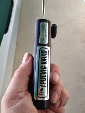 |
| The right tool for splicing braided line |
Splicing with this tool is nothing like using my old ones. How do I make the comparison? Let's try this: splicing double braid without this tool is like cutting a board with a hammer and a screw driver. You can do it, but it takes a lot longer, is a lot more work, and leaves you with a sub-optimal result.
 |
| The working end |
The Splicing Wand is basically a long tube containing a hidden snare. You slide the tool into the rope, grab the end you want to tuck, and slide the tool out. There's a specially-shaped tip on the tube, to keep you from snagging yarns along the way, an ingenious mechanism in the handle, to hold the tube in place while you work. You can clamp the tool in a vise if you want, leaving both hands free to deal with the rope, there's no taping or un-taping, no fid lengths to decipher, and very little physical effort needed to tuck.If you have double braid line on your boat, you need this tool. I'll say it again: Using Brion's tool, splicing old line was far easier than splicing new line was with my old tools. I don't think I can say it any better than that.
Why don't you have one?
Tuesday, March 3, 2015
Water Tight Conduit
Jeff and Anne have been doing a complete rebuild of s/v Pilgrim, a project which is way too large to qualify as a "small" boat project. Nevertheless, I thought you'd be interested in seeing how they created a water tite plumbing conduit under their icebox - it's a good example of fiberglass work:
Rainy, cool weather has delayed dropping Pilgrim’s rudder and forced me inside. Fortunately a small portable heater maintains a comfortable working temperature inside the boat.
Like the original construction we plan to have multiple bilge pump discharge hoses, a propane line, and likely a couple electrical wires running under the ice box. Now that we have fiber glassed close the gaps under the wall between ice box and the engine, any possible leaks from the hoses or spills in the cockpit locker could collect under the ice box. My initial solution was to drill a couple limber (drain) holes along the base of the wall separating the engine and the ice box. This solution had the downside of again allowing hot air from the engine access to the underside of the ice box. A more elegant solution would be to create a water tight conduit between the cockpit locker and area under the stove.
Initially I looked for a large diameter PVC or fiberglass pipe to cut in half and glass down to the hull. This search proved fruitless, but in my scrounging around I discovered some scrap pieces of 1” thick fiberglass paneling with a foam core. Ok… the conduit will be square.
Creating templates for the conduit side walls.
The conduit began as so many custom fabrications do… by using luan plywood strips and a glue gun to create a template. The templates of the 3” tall side walls were then transferred to the fiberglass panel.
Transferring the side wall template to the 1" thick fiberglass panel.
The more I worked with the 1” paneling the more I realize how ideal it is for this application. The foam will add to the insulation. The strength of this stuff when laid up with heavy mat will add structurally to the hull.
Ready to tab side walls to hull and adjacent bulkheads.
After test fitting the side walls and cutting 1708 cloth tabbing, I glassed them down. To minimize the risk of chafing hoses, I added a nice fillet along the inside corners.
Test fitting the top section.
Once the side walls cured, I was able to lay out the top section.
Beveling the long edges along the top to allow the fiberglass cloth to smoothly lie over the corner. After filling any gaps with thickened epoxy, I laid a single piece of 1708 cloth across the top ad down the sides.
Fiberglass work on conduit complete.
Once all the epoxy had cured, I sanded down any rough edges.
Conduit complete.
The outside dimensions of the conduit look large, but it incorporates one inch of foam insulation.
More images and notes from this on-going project as available in the Ice Box Rebuild Photo Album.


Subscribe to:
Posts (Atom)


